Frequency and Pulse outputs
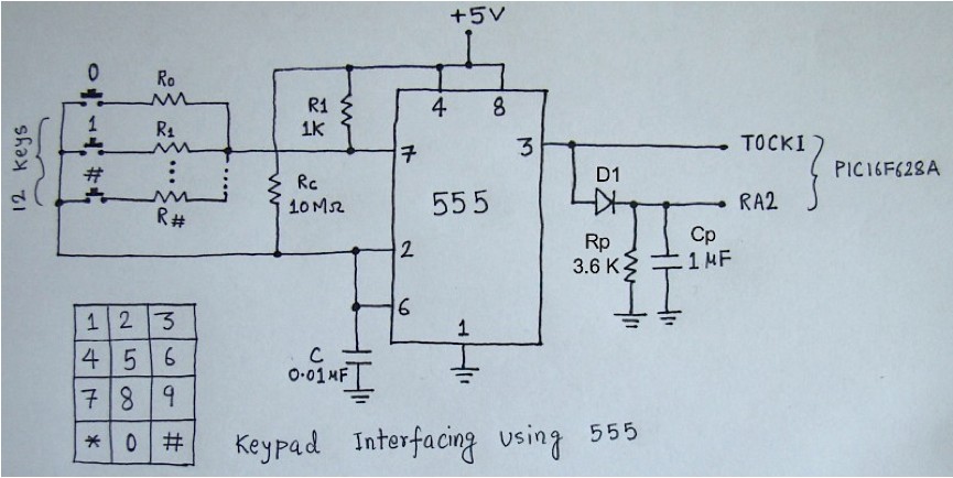
There are two outputs in this circuit. One is the frequency output derived directly from pin 3 that is fed to the T0CKI (Timer0 input) pin of a PIC16F628A microcontroller for counting. The second one is the smoothed pulse output using a capacitor Cp at the output of 555. When a key is pressed, the train of pulses at the output of 555 is smoothed out to a single pulse by the capacitor. This pulse is to signal the microcontroller when a key is pressed. The Rp (3.6 K) resistor provides the discharge path for the capacitor when the key is released so that another pulse would appear for next key press. The diode (D1) isolates the two outputs.
Significance of Rp and Cp values
The value of Rp is not picked randomly, it has its significance. If Rp is too high, there will be a long waiting time between any two key presses as the capacitor takes longer time to discharge through a higher resistance. Meanwhile, the value of Rp could not be too low that the capacitor voltage drops significantly between two successive pulses at the 555 output. With Rp=3.6 K and Cp = 1 uF, the RC time constant becomes 0.0036 s. It means that if the 555 output frequency is 278 Hz (1/0.0036), the voltage across the capacitor could fall down to 63% of its peak value in between the two consecutive pulses. This means the current values of Rp and Cp are not good enough to smooth out the signal. Therefore, the values of Rp and Cp must be chosen such that the RC time constant should be sufficient enough to smooth out the entire frequencies of operation and meanwhile it should be low enough that the user could press keys in sequence with minimum wait time. The current values of Rp and Cp introduces about 5 ms wait time and we don’t press keys that fast. Besides, the minimum frequency output is 1516 Hz (from the table above) which is much higher than 278 Hz.
Role of Rc resistor
If you look at the circuit diagram you will see a Rc (= 10 MΩ) resistor that is permanently connected between Vcc and C. This resistor plays a very interesting role. When you release a key, the astable multivibration is stopped because there is no R2 in the circuit. We know that the output stage of the 555 IC has a R-S flip-flop, the complement of which actually appear at the 555 output. Suppose the flip-flop was reset (which means the 555 output is high) at the moment when the key was released. Then there will be no way for the output to reset to 0 if the path through R2 is broken until we provide an alternative recharge path for the capacitor C. Once the capacitor gets charged to 2Vcc/3, the output will be zero again. Remember, we have to make sure that the output falls to zero before pressing another key. So Rc takes care of this. The high value of Rc (10 MΩ) makes sure that it has little impact on the charging of C during normal operation. If you didn’t get this part, please refer the functional block diagram of the 555 timer IC.

Part 3. Connecting to the PIC16F628A, Software, Demonstration.

