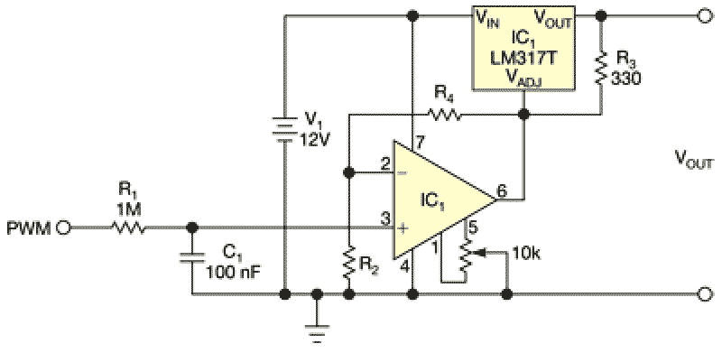
The LM317T from National Semiconductor is a popular adjustable-voltage regulator that provides output voltages of 1.25 to 37V with maximum 1.5A current. You can adjust the output voltage with a potentiometer. The circuit in Figure 1 replaces the potentiometer with an analog voltage that you can control from a PWM (pulse-width-modulation) signal. You control this signal with a microcontroller or any other digital circuit. You can use the same microcontroller to dynamically monitor the output and adjust the LM317T.
 |
|
| Figure 1. | This circuit replaces a potentiometer with an analog voltage that you can control from a PWM signal. |
Using an RC lowpass filter and an op amp, you can convert the PWM signal to a dc level that can adjust the LM317T’s voltage output. Varying the pulse width of the input signal lets you generate an analog voltage of 0 to 5V at the output of the lowpass filter. The op amp multiplies the voltage to achieve the desired voltage range.
For scenarios in which you must multiply the input voltage by two, the LM317T’s adjustment pin receives 0 to 10V. Its output-voltage range is 1.25 to 11.25V. The equation
VOUT = VADJ + 1.25V
governs the LM317T’s output voltage. You can change the op amp’s gain by choosing proper values for R4 and R2. You must be able to remove offset voltages from the op amp. Use an op amp, such as a National Semiconductor LM741, with null adjustment. The selection of values for the capacitor C1 and resistor R1 for the RC lowpass filter depends on the PWM signal’s frequency. This circuit uses values for a 1-kHz PWM signal.
You can improve the circuit by replacing the RC lowpass filter with an active filter and then feeding a feedback signal from the circuit’s output into the microcontroller for dynamic adjustments.
