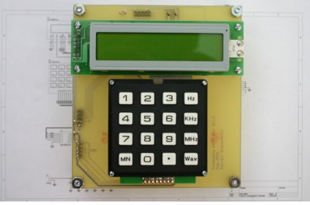
This project didn’t look complicated but it was. The MCU part is really simple: just some code for the Display, Keypad and DDS Communication.
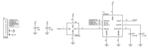
A DDS AD9833 from Analog Devices is a chip that is driven by a hi-frequency oscillator. I used a 50 Mhz clock. Inside this IC there is a big divider that goes down to less than 1Hz. The resulting clock is passed to another counter which is connected to a Sine ROM table. If you need a triangle wave, the counter is directly connected to the output. For a square wave, the signal which drives the counter is redirected to the primary output.
Features
- Frequency from 1Hz to 5Mhz
- Accuracy of 0.1Hz
- Square/Sine/Triangle Output
- Variable duty cycle
- 5V TTL output
- Output up to +15v to -15v peek to peek
- Adjustable DC Offset from +15v to -15v
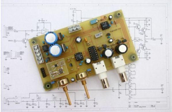
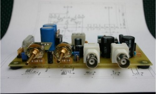
Once my MCU Board on ATmega32 and the DDS board were done, I connected everything together and a cool sine wave was coming out of my DDS ranging from 1Hz to 5Mhz. I thought to myself that this project was almost done…. beeeeeeeeeep, wrong again! The worst part was to come. It's not so easy to amplify a signal of 400mv to +/-15v, 300ma at 5Mhz. First you CAN'T prototype this on a bread board. So I built more than 5 PCB's. Also, I had to find a very high speed Op-Amp that came in a package suitable for prototyping. I chose the LM7171 for its low cost and DIP package. With an Op-Amp like this you must have decoupling capacitors on the – and + side to GND VERY CLOSE to the IC (each Op-Amp separately).
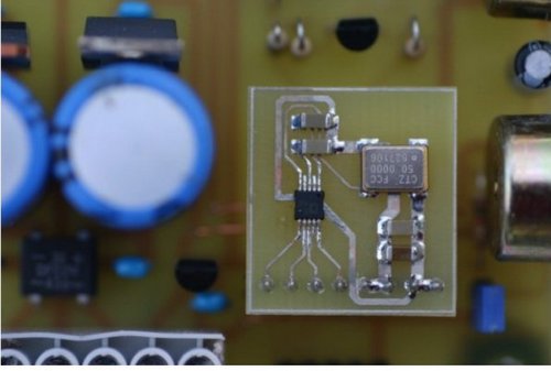
As you will see I mounted the DDS on a small PCB. This animal is so small that I was not sure that I could solder it. If I could then the DDS could be used on another mother-board.
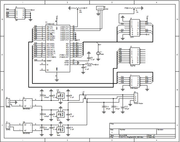
MCU Schematic
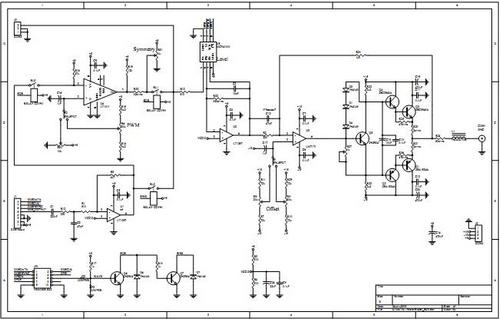
DDS Module Schematic
Output Analog Part of DDS generator
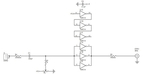
TTL Ouput
Note: The AD9833 DDS datasheet rates it for 25 Mhz, but in the preliminary datasheet it was rated for 50Mhz. I made my project work at 50 Mhz and there was no problem. Just don't try it for final production. The higher the clock rate, the better the output signal will be.
Downloads
Source Code and HEX-file - download