The classic Colpitts oscillator circuit in Figure 1 generates a clock signal with a fixed duty cycle. By replacing CMOS inverter gate IC1A with a voltage comparator (Figure 2), you can obtain a more versatile and more useful clock generator. You can set not only the oscillation frequency but also the duty cycle.
 |
|
| Figure 1. | A typical Colpitts oscillator uses an inverter and has a fixed duty cycle. |
You must use the comparator in an inverting configuration, which introduces a 180° phase shift. That shift, along with an additional phase shift of 180° from the capacitor-input network, lets the circuit oscillate. The circuit compares the sine wave at the output of the capacitor-filter network with the reference voltage, which drives the output of the threshold comparator high and low.
 |
|
| Figure 2. | A comparator lets you vary the duty cycle based on resistors R1 and R2. |
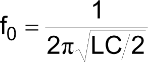
The network sets the oscillation frequency as follows:

where fO is the oscillation frequency. With a suitable choice of the values of inductors and capacitors, the circuit can oscillate at frequencies as high as 10 MHz.
The output clock’s duty cycle depends on the reference voltage, which you can easily set through the voltage divider comprising R1 and R2. Unfortunately, the mathematical relationship between the reference voltage and the duty cycle is nonlinear because the sine wave at the output of the capacitor-input-filter network is not a linear function. Also, its amplitude is not constant but depends on the duty cycle of the output clock. You can easily obtain this mathematical relationship by testing the circuit with an inductance of 10 μH and a capacitance of 10 nF.
Table 1. Oscillator duty cycle based on reference voltage
|
Reference voltage
(V) |
Duty cycle
(%) |
|
0.5
|
15.2
|
|
1
|
28.3
|
|
1.5
|
37
|
|
2
|
43.5
|
|
2.5
|
50
|
|
3
|
56
|
|
3.5
|
62.6
|
|
4
|
71.5
|
|
4.5
|
85.4
|
You can use any high-speed comparator with rail-to-rail inputs and outputs, such as the MAX987 from Maxim, to achieve a wider input range for the reference voltage. That wider range gives you wider control of the duty cycle, although you can’t reach the minimum duty cycle of 0% or the maximum duty cycle of 100%.
The propagation delay, TPD, of the comparator introduces a further phase shift of value Δφ=2πfOTPD, where Δφ is the phase shift. The capacitor-input network compensates for the phase shift, slightly reducing the oscillation frequency. For safe operation of the circuit, you should vary the reference voltage by 0.5 to 4.5V. The duty cycle varies from approximately 15 to 85% (Table 1). You can produce a bipolar output signal if you use a dual power supply.
