Rajendra Bhatt, Nepal
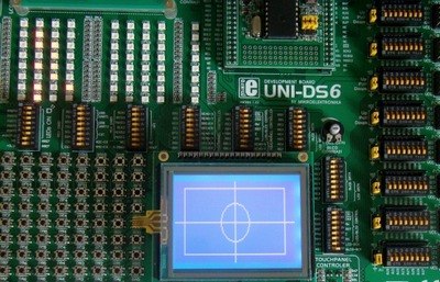
The use of a graphical LCD (GLCD) drastically changes the look of your project. It provides more freedom for presenting data than the HD44870 based character LCDs. Today we will see how to interface a KS0108 (name of the display controller chip) based GLCD to a PIC microcontroller. Since GLCDs are real resource hungry devices (in terms of required I/O pins and memory), a bigger size Microchip PIC microcontroller (PIC16F887, which has 36 I/O pins and 14KB flash memory) is selected for this experiment. I am using MikroElektronika’s UNI-DS6 development board to demonstrate this project, but the circuit setup can also be made on a breadboard.

Theory
The graphical LCD used in this experiment is Winstar’s WDG0151-TMI module, which is a 128×64 pixel monochromatic display. It uses two Neotic display controller chips: NT7108C and NT7107C, which are compatible with Samsung KS0108B and KS0107B controllers. The KS0108B (or NT7108C) is a dot matrix LCD segment driver with 64 channel output, and therefore, the WDG0151 module contains two sets of it to drive 128 segments. On the other hand, the KS0107B (or NT7107C) is a 64-channel common driver which generates the timing signal to control the two KS0108B segment drivers. The KS0108B and KS0107B are a very popular controllers and have made their way into many graphical LCDs. The internal block diagram of the WDG0151 GLCD module is shown below.

Internal block diagram of a KS0108B (NT7108C) based 128x64 pixel GLCD module
The NT1707C drives the 64 display lines, COM1 – COM64. The first NT7108C drives the left half segments (SEG1 to SEG64) and the second one drives the right half segments (SEG65 to SEG128) of the display. The two halves of the display can be individually accessed through the chip select pins (CS1 and CS2) of the two NT7108C drivers. Each half consists of 8 horizontal pages (0-7) which are 8 bits (1 byte) high. This is illustrated in the drawing below.

GLCD pages
Starting from page 0 on the left half (/CS1 = 0) if you transmit one data byte, it will appear on the first column of page 0. If you repeat this 64 times, then switch to the second half, and repeat until 128th position is reached, the first 8 display lines will be plotted. The next 8 lines can be plotted similarly by switching to page address 1. The total amount of bytes needed for a complete display frame (128×64 pixels) is, therefore, 2 × 64 pixels × 8 bits = 1024 bytes.
The Winstar WDG0151-TMI module does have an internal negative voltage generator circuit which provides a negative voltage at VEE external pin. An external potentiometer (usually 10 K) is connected between Vcc and VEE pins to set the LCD working voltage (contrast) at Vo pin. The pin diagrams of KS0108 based GLCDs is not standardized and it is therefore, important to read the manufacturer’s datasheet for correct wiring of a GLCD module. The following table shows the pin descriptions of Winstar WDG0151-TMI module. It has altogether 20 pins. The first two pins (1 and 2) are the chip select pins for the left and right display controller. They are active low in a WDG0151-TMI module, but they could be active high in some other models. That’s why I said reading manufacturer’s datasheet is very important. The WDG0151-TMI module operates at 5.0 V power supply. Pin number 6 is Data/Instruction (also called Register Select, RS) select pin. The 8-bit data fed to D0-D7 pins of the GLCD is received by the LCD controller chip as an instruction if D/I = 0, and as data if D/I is 1. The R/W and E pins have similar functions as in a HD44780 based character LCD module. A fixed resistor value must be connected in series with the back-light LED (pins 19 and 20) to limit the current.

Pin description of Winstar WDG01510 GLCD module
The KS0107/KS0108 does not have a character generator so this must be implemented in the microcontroller firmware. The LCD controller supports a handful of instructions which are summarized in the table shown below. Note that the RS (D/I) pin is high only during data read and data write operations, and stays low when a transmitted byte is an instruction.
Part 2 - Schematic, Firmware for the PIC microcontroller to initialize the GLCD

