Application Note AND9140/D
December 2013
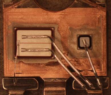
IGBTs generally require a more complex set of calculations to determine the die temperatures than do most power semiconductors. This is due to the fact that most IGBTs are co-packaged and include both an IGBT and a diode die in the same package. In order to know the temperature of each die, it is necessary to know the power dissipation, frequency, thetas and interaction coefficient for each die. It is also necessary to have the thetas for each device and the psi value for their interaction.
This application note will explain, in simple terms, how to measure the power and calculate the temperature rise of the diode and IGBT dice.
Loss Components
Depending on the circuit topology and operating conditions, the power losses between the two die can vary considerably. The losses in the IGBT can be broken down into the conduction and switching (turn-on and turn-off), while the diode losses are the conduction and turn off losses. Accurately measuring these losses generally requires the use of an oscilloscope with voltage and current probes to monitor the waveforms during operation of the devices. It will be necessary to utilize math functions to measure the energy. When the total energy for a switching cycle has been determined, it can be translated to power by dividing by the time of the switching period. ....
![]() Download Application Note AND9140/D (509 Kb)
Download Application Note AND9140/D (509 Kb)

TO-247 Package Showing IGBT Die (Left) and Diode Die (Right)