A basic combination of a photovoltaic panel, multiple LEDs, and a small dc-dc regulator can provide light in dark corners while also offering a modest auxiliary dc-power rail.
A solar-powered, daytime-only lamp without a battery for energy storage may seem to be a marginally useful device, but many areas in homes and offices are relatively dark, even during the daytime. This "day lamp" provides light throughout the day from a nearby solar panel, and also provides regulated auxiliary power of 0.5 W for a small load (such as an FM receiver) at very small incremental cost.
The solar day lamp (Fig. 1) uses a photovoltaic (PV) panel with a 10-W rating. The voltage at maximum power, VMP, is 17.3 V, and two identical arrays of LEDs are connected in parallel to the output of this panel. Each array consists of five white LEDs (LEDs 1-5 and LEDs 6-10) rated at 1 W each, and has series resistance of 22 Ω and power rating of 2 W (R1 and R2) to control the current into its LED string.
 |
|
| Figure 1. | The solar day-lamp schematic shows two identical strings of LEDs, each fed by a basic current source using a current-defining resistor. |
The output of the PV panel is connected through a switch to a switched-mode power supply (SMPS), which provides the regulated power (Fig. 2). The bulk capacitor at the SMPS input reduces variations in LED light that would occur due to changing levels of audio output at the FM receiver as load.
 |
|
| Figure 2. | Here’s a block diagram of the day lamp with a small, regulated switched-mode power supply for powering auxiliary loads such as a small FM receiver. |
There are several low-cost switch-mode ICs, and three widely available ICs with identical switching frequency, output voltage, L-C values, and load resistance were bench-evaluated for this application: the LM3524, MC34063, and LM2575. The converter implementation based on the MC34063 produced the least amount of drop in PV voltage (VPV) under identical conditions, due to its lower quiescent current and the lower saturation voltage of switching device. Thus, it was selected.
 |
|
| Figure 3. | The circuit diagram of the dc-dc converter for the FM receiver (5 V/100 mA) includes a "home-made" 220-μH inductor. |
The input supply voltage (VIN) is connected to pin 6 through ON/OFF switch SW in the dc-dc converter using the MC34063 (Fig. 3). Bulk capacitor C1 (2200 µF) is connected after the switch to minimize the voltage variations caused by changes in light intensity. Capacitor C2 (1000 pF) at pin 5 sets the switching frequency to 33 kHz.
 |
|
| Figure 4. | The actual assembled circuit of the dc-dc converter shows basic construction on perforated phenolic board and point-to-point wiring. |
The output is filtered by L1 and C3. The 220-µH inductor is made by winding 48 turns on a toroidal core (suitable cores with a diameter of about 10 mm and length of 20 mm can be salvaged from old computer cables). Resistors R1 and R2 were selected to provide 5 V at output, and the output voltage can be changed by changing the value of R1. For an output of 6 V, R1 should be 27 kΩ; for 4.5 V, R1 will be about 39 kΩ. The assembled circuit is shown in Figure 4, and Figure 5 shows the complete system.
 |
|
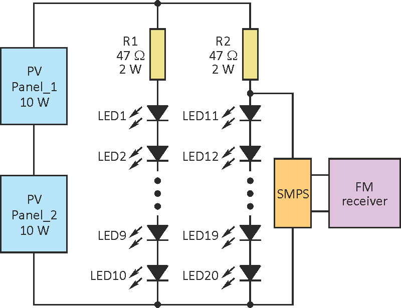
| Figure 5. | The day lamp can also use two PV panels, but the topology must be adjusted to avoid excessive voltage on the regulator. |
It’s possible to design a day lamp with two PV panels connected in series to capture more light (Fig. 6). In this case, however, the maximum PV voltage can exceed 40 V while the MC34063 is rated up to a maximum voltage of 40 V. To overcome this problem, the dc-dc converter is connected across one of the two LED arrays, instead of directly connecting to PV output. Each LED array contains 10 LEDs and the maximum forward voltage of each LED will not exceed 3.5 V; thus, the voltage across 10 LEDs will not exceed 35 V.
 |
|
| Figure 6. | The complete system includes solar panels, LED arrays, and a small FM radio. |
