Glen Brisebois
EDN
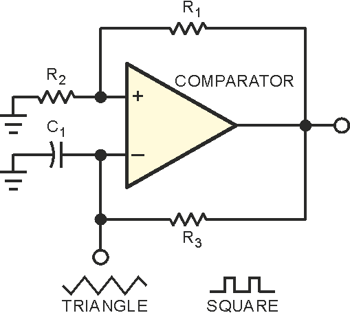
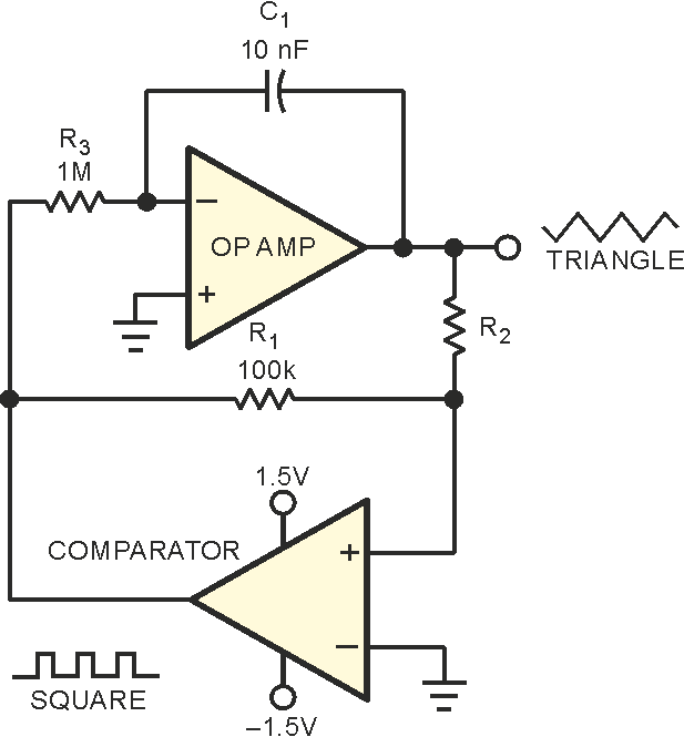
Ideal triangle waves involve infinite d2V/dt2, so high-fidelity triangle waves entail very high bandwidths. Micropower circuits have fairly low bandwidth, so generating good triangle waves with such circuitry becomes problematic. The circuits of Figure 1 show two methods of generating triangle waves. The solitary-comparator circuit uses a relaxation-oscillator approach with the triangle approximation assuming an RC (exponential) nature (Figure 1a). When you need better linearity, adding an integrator improves the triangle approximation (Figure 1b). Both circuits include a hysteretic-feedback path, as well as an RC or integrator feedback path comprising R3 and C1. The hysteretic-feedback path keeps changing the direction of the RC integrator and setting the new target voltage, and the RC integrator sets the rate of change toward the new target. These circuits are robust and find wide usage.
|
||||||
| Figure 1. | These popular methods of generating triangle waves have drawbacks, especially when your design requires low-power operation. |
|||||
The problem arises when you simultaneously require ultralow power consumption and relatively high-frequency operation. This scenario makes phenomenal demands on the micropower op amp. Consider that, every time the comparator reverses direction, it slams an instantaneous current into or out of the op amp's output through the two feedback paths. This situation would be acceptable, except that the amount of current it slams is greater than the op amp's total supply current. The result is a disastrous-looking waveform with enormous glitches stemming from the fact that the op amp cannot provide the instantaneous output-switch current demands. You can gain some improvement by increasing the resistor values and reducing the capacitor values. However, the improvements are only incremental, and the circuit becomes noisier and more susceptible to interference.
 |
||
| Figure 2. | A simple CMOS inverter provides high-bandwidth current assist, improving the waveform drastically with minimal impact on supply current. |
|
But take heart; a simple and inexpensive solution is at hand. Why not let a CMOS inverter provide the instantaneous current and let the op amp simply provide the precision linearizing current? Figure 2 shows the method. The circuit is identical to that of Figure 1b, except that the op amp need not provide the instantaneous switch current. Instead of the drastic change in output-current polarity at the triangle peaks, the op amp's output current slowly crosses zero at midsupply. In the improved waveform, the total supply current at 280-Hz operating frequency is 6.2 µA.


