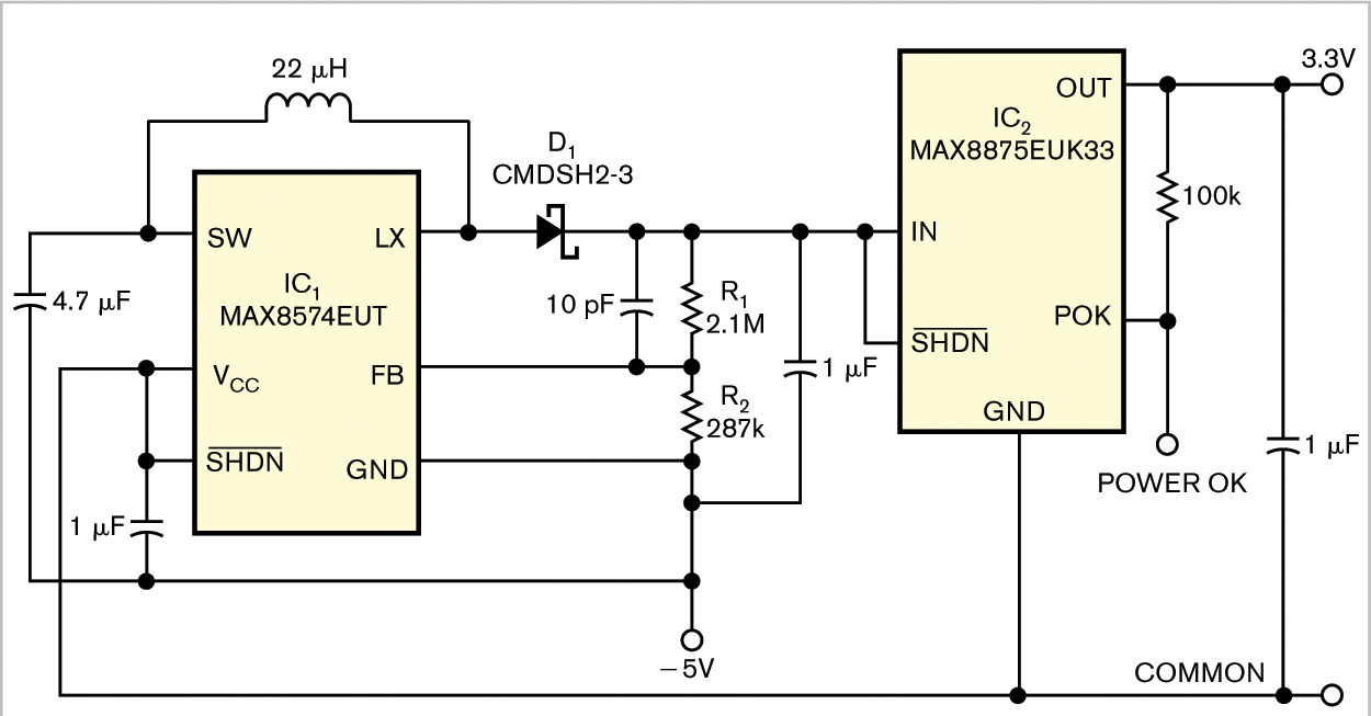
You can obtain a precise, positive-output voltage from a negative-voltage supply with a boost converter and a linear regulator. The input and output capabilities of the circuit in Figure 1 depend on the allowable I/O voltages of IC1 and IC2. In this case, IC1 and IC2 convert a –5V input voltage to a 3.3V output voltage.

Click, for enlarge
Figure 1 A two-IC circuit converts a –5V input to a 3.3V output.
IC1 is a boost converter that accepts –5V when its VCC pin connects to common ground – that is, the ground of the negative-power-supply input. Voltage divider R1/R2 at IC1’s output provides feedback that sets the output voltage 10.5V above IC1’s ground pin. With the feedback-threshold voltage factory-set to 1.226V, you can choose values for R1 and R2 using this equation:
(1.226V/R2)×(R1+R2)=10.5V.
Current through R1 and R2 should be at least 2 µA. The IC1 output, which is IC2’s input, is 10.5V higher than –5V, which is 5.5V with respect to common ground.

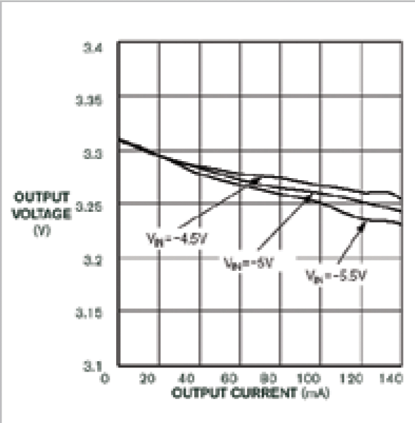
Figure 2 The circuit's output voltage drops as current increases. Plots indicate source voltages of -4.5, -5, and -5.5V.
IC2, a linear regulator whose ground pin connects to the common ground, accepts input voltages as high as 6.5V. Its output is factory-set at 3.3V. Figure 2 shows the output voltage versus the output current for the circuit in Figure 1 with input voltages of –4.5, –5, and –5.5V.
