Soumitra Bhattacharjee
EDN
In PIC microcontrollers, the MSSP (master synchronous serial port) module uses multiplexed pins for the I2C and SPI peripherals. There is typically no issue using either of the two peripherals. But what if both peripherals are needed simultaneously, without changing the microcontroller?
The following circuit was developed for a portable instrument using a 28-pin PIC MCU from Microchip Technology running an RTC (real time clock), EEPROM, and COG (chip on glass) LCD on the I2C bus, and a digital pot and microSD card on the SPI bus. The implementation has performed flawlessly for us.
 |
||
| Figure 1. | This circuit allows the use of the SPI and I2C bus using the same peripheral pins. | |
The circuit in Figure 1 allows the use of the SPI and I2C bus using the same peripheral pins and two extra GPIO pins without a significant increase in the bill of materials, using just 4 MOSFETs. The MOSFETs we used are readily available logic level N channel type. Examples include the 2N7000 and the BSS138, both from ON Semiconductor. Both were tested, and performed satisfactorily.
The multiplexed pins for SCK/SCL and SDA/SDI are switched by this MOSFET combination by turning on the gate for the respective peripherals by the microcontroller. In the firmware, the required peripheral is turned ON by making the respective GPIO HIGH and driving the other GPIO LOW before initializing the respective bus.
|
||||
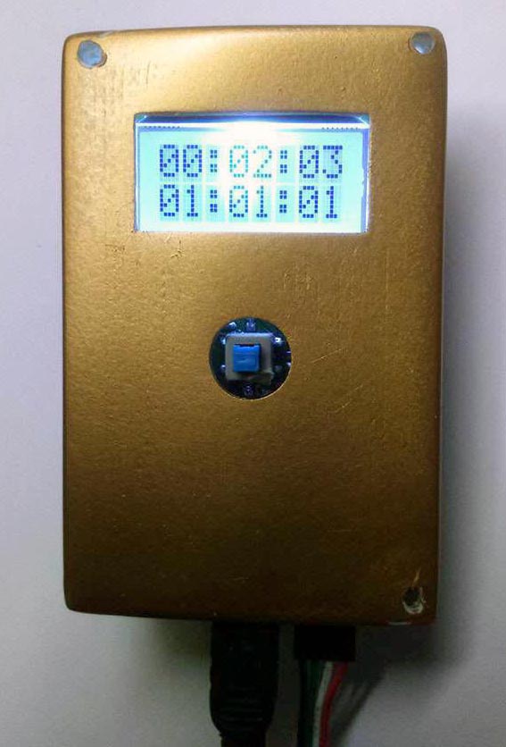
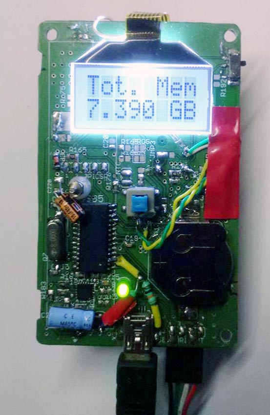
| Figure 2. | The actual device in operation where the peripherals are switched automatically. | |||
The connections are straightforward, the MOSFET DRAIN pins connect to the MCU pins except the FET-DI (MOSI) MOSFET, whose SOURCE pin connects to the MCU. The pull-up resistors for the I2C connections should be added to the SOURCE pins of the MOSFETs on the I2C side.


