If you use a function generator, you may occasionally require a sine-wave output at a higher frequency than the generator can provide. If your function generator also produces a triangle-wave output, you can use a frequency doubler to extend the generator’s available frequency by as much as a factor of two. A previously published Design Idea describes a triangle-wave-driven frequency-doubler circuit employing op amps that produce output frequencies limited to about 20 kHz (Reference 1).
This Design Idea describes a frequency doubler that provides a sine- wave output with a frequency of 4 to 6.7 MHz, with an output level that can range from 110 mV p-p to 1.30 V p-p into a 50 Ω load. As Reference 1 describes, applying a symmetrical triangle wave to a full-wave rectifier produces a triangle wave of twice the input frequency and offset by a dc level. Any asymmetry in the input waveform allows some of the input signal’s fundamental frequency to pass through to the output. Also, the circuit’s input transformer, T1, may cause amplitude or phase imbalance, allowing some of the input signal to pass through to the output.
 |
||
| Figure 1. | A full-wave rectifier, buffer, and lowpass filter produce a sine-wave output at twice the frequency of a triangular-wave input. |
|
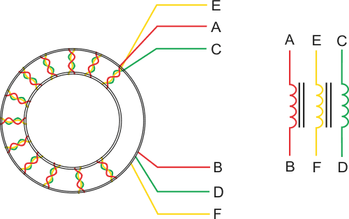
To construct a wideband transformer with good amplitude and phase balance, twist three AWG #30 enameled wires together at about 10 twists/in. Wind seven turns of the bundled wires onto a Fair-Rite 2643002402 toroidal core. (Each pass through the core’s central opening counts as one turn.) Connect the wires as shown in Figure 1. (Refer to Reference 2 and Figure 2 for additional information on this type of transformer.) This technique results in a wideband transformer with good amplitude and phase-balance characteristics.
 |
||
| Figure 2. | Transformer T1 from Figure 1 consists of three windings on a toroidal ferrite core. For ease of assembly, twist three wires of different colors in a bundle to form the windings. |
|
To achieve maximum input-frequency attenuation, use a matched pair of Schottky diodes for D1 and D2. However, the prototype produced high-quality signals with unmatched Schottky diodes. In Figure 1, diode D3 applies a small negative bias to D1 and D2 that allows operation at low signal levels. Capacitor C1 passes the rectified and frequency-doubled triangle wave to the bases of a complementary emitter follower comprising Q3, Q4, and associated components. A simple, two-element lowpass filter at the follower’s output removes higher frequency harmonics. Use any 1.6-µH inductor with a Q of 20 or greater for L1. Although an inductor with a Q as low as 10 will not noticeably change the filter’s frequency response, a value lower than 20 increases the inductor’s insertion loss and decreases the maximum available output-signal amplitude.
A simple, two-element, lowpass output filter provides adequate performance for a symmetrical-triangle-wave input because the output’s frequency components consist of the doubled input frequency signal and only the desired output signal’s odd harmonics. For a 5-MHz output, the third harmonic occurs at 15 MHz with an amplitude of –19 dB relative to the 5-MHz signal. The lowpass filter imposes 15 dB more attenuation at 15 MHz, diminishing the 15-MHz signal to –34 dB relative to the 5-MHz output signal and attenuating higher order harmonics to even lower levels.
The complementary emitter follower’s unfiltered output signal consists of a triangle wave of twice the input signal’s frequency, plus odd harmonics of the doubled input frequency. For example, applying a 2.5-MHz triangle wave to the circuit’s input produces a 5-MHz triangle-wave signal at the lowpass filter’s input. For a nearly perfect triangle wave, the filter’s input consists of a 5-MHz fundamental and only its odd harmonics. At –19 dB below the 5-MHz signal, the 15-MHz third harmonic represents the closest spurious signal and one that you can easily filter.
To use the circuit at higher frequencies, divide the values of output-filter components L1 and C8 by a factor of FNEW/5, where FNEW represents the desired output frequency in megahertz. For example, a nominal output frequency of 20 MHz requires division of the values of L1 and C8 by a factor of four, producing new values of 0.4 µH and 140 pF, respectively. Simulating the circuit with the revised filter in Spice shows adequate harmonic rejection over an output range of 16 to 26.8 MHz. Although designed for 5-MHz operation, the remainder of the circuit works well at 20 MHz without additional modifications. This frequency doubler also accepts a sine-wave input signal. However, the circuit’s unfiltered output contains higher levels of the desired signal’s even- and odd-order harmonics and requires additional filtering to produce a high-quality sine-wave output.