Today, although the wireless technology grows very fast, the long distance funicular communication still keeps its popularity. The reason is obvious that cost and complexity is high at the wireless communication.
RS232 is one of the most used, easy to develop and easy to apply communication protocol. We generally encounter to this standard at the MCU applications. But it has some restrictions. It allows us to use maximum 15 meters cable. Good wiring, low baud rates and less noisy mediums may allow us to exceed this limit a little more. The main problem here , when the distance increases, the noise at the common ground line also increases. Another issue, RS232 allows only two devices to communicate reciprocally. More than two devices can not communicate at this line and we need another solution for this situation.
RS485 is the standard that solves this problems. The main difference is, RS485 transfers the data depending on the potential difference between the two communication wires. The polarity defines the logic state of the signal. You can transfer data up to 1220 meters far away and with a rate up to 10 Mbs. 32 devices can join the RS485 network.

Converter Operation
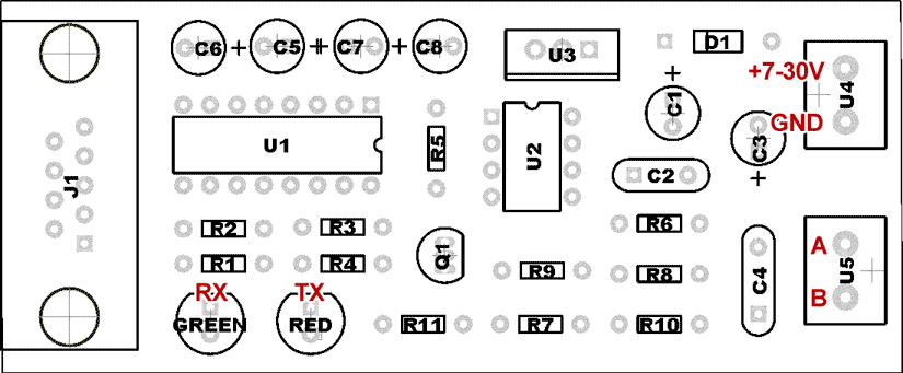
While transferring the data, MAX232 converts the signal coming from the DB9 connector to TTL/CMOS level. Then MAX485 transfers the input signal coming from the MAX232 to the RS485 line as a voltage difference. While receiving the data, MAX485 detects the data at the RS485 line and transfers it to MAX232 then output can be taken from the DB9 connector.
Converter controls the "Receive" and "Transmit" modes automatically.
Component List
|
R1, R2 |
1K 1/4W Resistor |
|
R3, R4, R5, R11 |
2.2K 1/4W Resistor |
|
R6, R7 |
560 Ohm 1/4W Resistor |
|
R8, R9 |
47 Ohm 1/4W Resistor |
|
R10 |
120 Ohm Resistor |
|
C1 |
10uF 50V Electrolytic Capacitor |
|
C2, C4 |
100n Polyester Capacitor |
|
C3 |
10uF 16V Electrolytic Capacitor |
|
C5, C6, C7, C8 |
1uF 16V Electrolytic Capacitor |
|
D1 |
1N4007 Diode |
|
L1, L2 |
Red and Green LEDs |
|
Q1 |
BC327 PNP Transistor |
|
U1 |
|
|
U2 |
|
|
U3 |
|
|
J1 |
DB9 PC Mount Female Connector |
|
U4, U5 |
2 Terminal PCB Terminal Block |
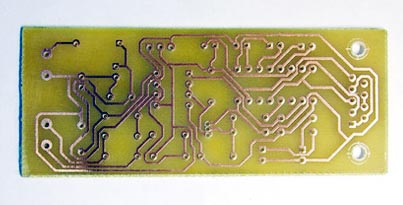
The PCB file is provided in pdf format. You can apply it to the board by using the ironing method.

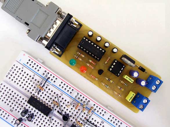
Red LED indicates the transmitting and green one indicates the receiving process. When there is no data transfer, to keep the data line at a constant voltage leve , two 560 Ohm resistors are connected to the line. One of them is powered and the other one is grounded.

The main advantage of this converter is, it can detect the incoming/outgoing data and switch the TX and RX modes of MAX485. It controls the DE and RE enable bits automatically. The RS485 lines A and B are taken from the screw terminal block. The connections are shown in the layout that is inside the downloadable zip package.
