In adjustable, frequency-selective RC networks, the reciprocal of an RC product, ωC = 1/RC, determines the corner frequencies of the network. If the adjustable elements are potentiometers with a linear-control characteristic – that is, taper – R(α) = αRP, where α is the normalized wiper position, 0 ≤ α ≤ 1, and RP is the potentiometer’s end-to-end resistance, then the corner frequencies are reciprocal functions of the potentiometer’s wiper position, and the frequency scale compresses at the high end of the adjustment range. This situation is usually undesirable because it complicates adjustment of the network at the high end. To make the frequency scale linear requires a control element with a hyperbolic taper – that is, something in the form

Such variable resistances are not generally available from manufacturers, but you can synthesize them using a linear taper potentiometer and a few other components.
 |
|
| Figure 1. | This simple circuit synthesizes a grounded variable resistance with a hyperbolic-control characteristic. |
Figure 1 shows a simple circuit for producing a ground-referenced variable resistance having the desired hyperbolic-control characteristic. Analysis of this circuit yields the following relationship between the control setting and the resistance from Node 1 to ground:

If you use this resistance in series or in parallel with a capacitor, the resulting corner frequency will be a linear function of α:

The minimum and maximum values for R1-0 are

and

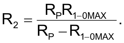
To design this circuit for specific values of R1-0MIN and R1-0MAX, choose RP > R1-0MAX and then compute

and

You can extend the basic circuit of Figure 1 to produce a floating variable resistance with hyperbolic taper (Figure 2). The value of the floating resistance between nodes 1 and 2 is

and the minimum and maximum values for R1-2 are

and

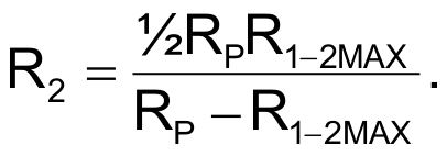
To design the circuit of Figure 2 for specific values of R1-2MIN and R1-2MAX, choose RP > R1-2MAX and then compute

and

Note that the value of the R3 resistors does not directly affect the value of R1-2(α). You should choose resistors that are large enough to not excessively load the op-amp outputs.
 |
|
| Figure 2. | You can realize a floating variable resistance, with hyperbolic taper, with this circuit. Note that fixed resistors with the same number are matched pairs. |
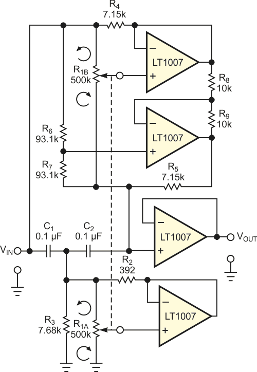
Figure 3 illustrates the application of the circuits in figure 1 and figure 2 to the design of an adjustable bridged-T notch filter with a linear frequency scale. The filter has a notch center frequency that is adjustable from 50 to 1000 Hz and a notch depth of –20 dB. These requirements and the choice of 0.1-µF capacitors for C1 and C2 dictate that R1-0 varies from 375 to 7503 Ω and that R1-2 varies from 6752 to 135,047 Ω. (A side benefit of using this technique is that it frees the designer from the restrictions of the limited number of standard end-to-end resistance values that potentiometer manufacturers offer.)
 |
|
| Figure 3. | The basic circuits of figures 1 and 2 have been used in the design of a bridged-T notch filter with a variable notch center frequency and a linear frequency scale. |
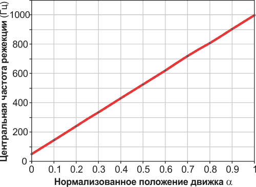
Figure 4 plots the Spice-simulated notch center frequency for the circuit of Figure 3 against the normalized wiper position. The notch center frequency is a linear function of the control position.
