A silly simple and ubiquitous circuit network is a variable resistance consisting of the series connection of a manually adjusted rheostat-connected pot and fixed resistor shown in Figure 1.
 |
|
| Figure 1. | Classic variable resistance with the series connection of a manually adjusted rheostat-connected pot and a fixed resistor. |
The availability of pots and resistors spanning ohms to megohms makes optimum choices of Figure 1’s component values obvious and easy. But if an application calls for using a digital potentiometer (Dpot), the situation gets more – ahem – interesting.
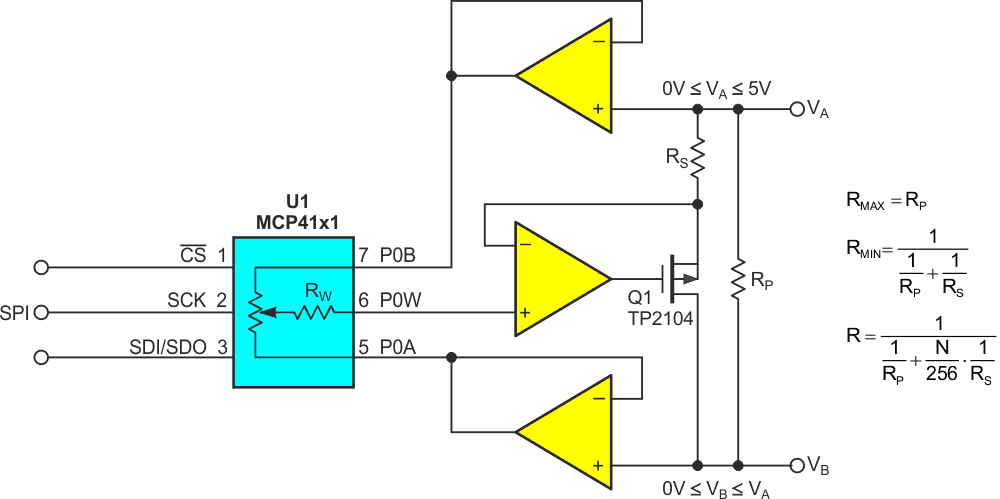
Dpots are only available in a relatively narrow range of resistance compared to manual pots. They also suffer from larger wiper resistances and wider tolerances. These limitations make them a dubious choice for implementing precision rheostats if Figure 1’s classic passive topology is solely relied upon. Figure 2 offers an active and more Dpot-friendly alternative.
 |
|
| Figure 2. | Synthetic Dpot evades problems using FET shunt, precision fixed resistors, and op-amp. |
Here’s how it works.
Despite the fact we’re implementing a variable resistance, Dpot U1 is operated in potentiometer mode. So, its resistance tolerance (±20% for the MCP41xx series) has little negative effect. The precision of RS and RP dominate. Likewise, Dpot wiper resistance is rendered purely academic by the pA input current and T ohms input impedance of A1. A1 and Q1 are connected as a programmable current source. Its output is proportional to the VA – VB voltage differential, thus forming a precise programmable resistance. This relationship makes current IAB linearly proportional to N.
Design equations are for appropriate resistances starting from specified RAB, RMAX, and RMIN are:


Figure 3 shows a typical design example for RMAX = 20k, RMIN = 1k.
 |
|
| Figure 3. | Synthetic rheostat design example where RMAX = 20k and RMIN = 1k. |
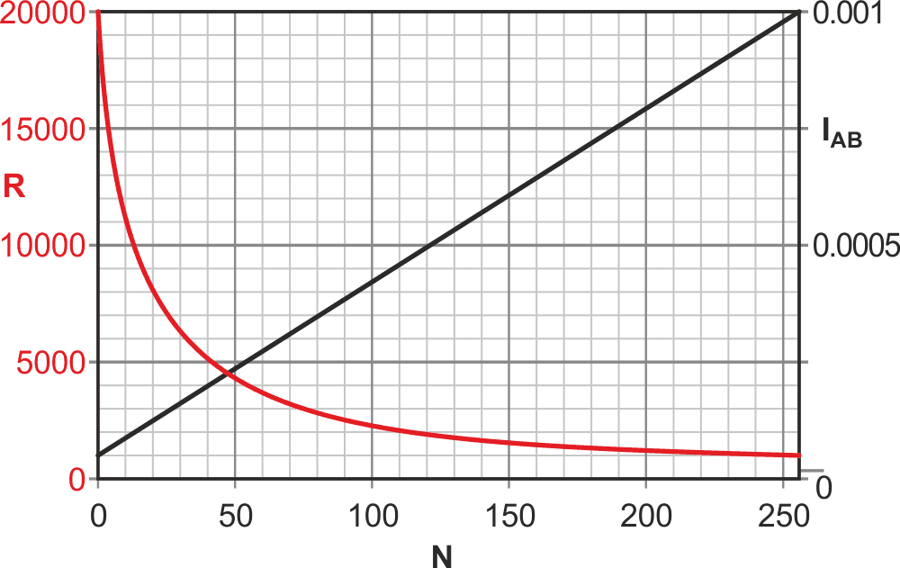
Figure 4 plots R and current per (VA – VB volts) as functions of N.
 |
|
| Figure 4. | Performance of Figure 3’s circuit with values shown, the linear relationship between N and IAВ conserves the Dpot’s limited 8-bit resolution. |
Note the accurately linear relationship between N and IAB current which does a good job of conserving Dpot limited 8-bit resolution.
A question arises: What if the required RMAX is larger than the RAB resistance of available Dpots? Figure 5 offers a practical (although admittedly somewhat busy) solution that can easily implement an accurate RMAX extending far into the multi-megohm range.
 |
|
| Figure 5. | Two buffer amps remove RAB from RMAX equation, allowing for an RMAX extending far into the megaohms. |
Another (stickier) question is: What happens if the polarity of VA – VB is subject to reversal? Figure 1 can accommodate this without a second thought, but it’s a significant problem for this design idea.
I’ll have to get back to you on that one!