Vassilis Papanikolaou
Introduction
This is a new design for a universal gear indicator that can be fitted to any motorcycle as an aftermarket accessory. Its main advantage is that its operation depends entirely on the gear shift lever movement, instead of connecting to speedometer and tachometer sensors (found in expensive commercial devices), which are rarely available in older motorcycles. It consists of a main circuit including a 7‑segment LED indicator, two Hall sensors that are attached to the motorcycle frame, and a small magnet placed on the gear shift lever.

The main circuit is based on an AVR ATTINY25/45/85 microcontroller, which reads the signals of the two Hall sensors and the neutral switch and outputs the current gear number to a 7‑segment LED indicator, through a 4026 counter/decoder.
- Download EAGLE files in .zip format
The source code is written in AVR-GCC (WinAVR) and can be programmed with the default fuses using an AVR programmer (default : ATTINY25 microcontroller and USBTiny programmer). The constants TOP_GEAR (number of gears, default : 5) and N_WAIT_TIME (minimum time to pass until neutral gear is detected, default : 500 ms) can be modified for different needs.
- Download source files in .zip format
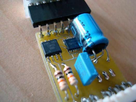
The suggested implementation for the main circuit is a small size, double-sided PCB, with SMD packages for the microcontroller and the decoder ICs. The 7-segment LED is placed in a secondary PCB, connected vertically to the main one in a modular fashion (see pictures). Two PCBs for different Kingbright LED footprints (red and blue) are also provided. The voltage regulator can be used for mounting as shown in the pictures. Don't forget to solder the four small vias under the two ICs !
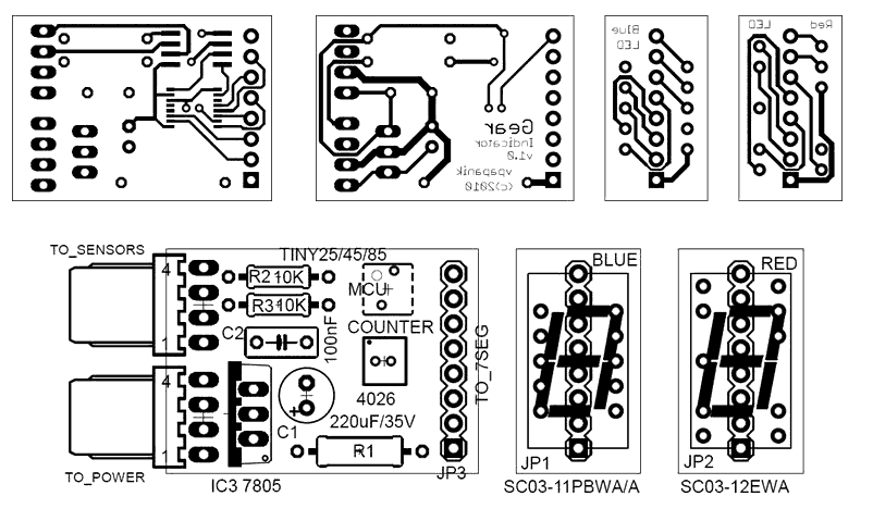
- Download PCB top layer in .pdf format
- Download PCB bottom layer in .pdf format
- Download PCB silkscreen in .pdf format
Parts List
|
Part |
Value |
Comments (for suggested PCB) |
|
R1 |
10 to 220 Ω ½W |
Depending on preferred LED brightness |
|
R2, R3 |
10 ΚΩ ¼W |
|
|
C1 |
220 μF / 35V |
Electrolytic capacitor |
|
C2 |
100 nF |
MKT/polyester capacitor |
|
MCU |
ATTINY25/45/85 |
Mouser Part 556-ATTINY25-20SU |
|
COUNTER |
4026 |
Mouser Part 595-CD4026BPWE4 |
|
IC1, IC2 |
Hall sensor |
Melexis US5881LUA (available from adafruit) |
|
IC3 |
7805 |
5V Regulator TO-220 |
|
BLUE |
Kingbright 0.3" |
Mouser part 604-SC03-11PBWA/A |
|
RED |
Kingbright 0.3" |
Mouser part 604-SC03-12EWA |
|
JPx |
Pin connectors |
As shown in silkscreen and pictures |
Photos
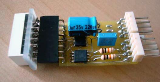
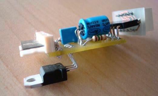
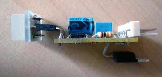
Connections


A successful circuit build will do a self-test when connected solely to 12V power (pins TO_POWER_1 and TO_POWER_2), by cycling through all digits on the 7-segment display (see video below). After the self-test, the current gear will be shown and can be changed by the shift lever movement. Note that a gear is changed when the magnet's south pole is drawn away from the sensor (north pole will not work). Moreover, if a neutral gear is detected (from the neutral switch connected to TO_POWER_4), the display resets to zero (also acting as a self-calibrating feature if anything goes wrong). Finally, when the power is turned off, the last shown gear is stored in the MCU's flash EEPROM and restored when the device is turned on again.

The following video shows the initialization procedure of the gear indicator :
- Download self test video in .avi format
Circuit protection
Due to special environmental conditions it is recommended to cover the circuit with plastic lacquer before installation.
Sensor cable
The following photos show the construction of the 4-wire sensors cable that is plugged to the TO_SENSORS connector. The visible sensor pin parts should be covered with plastic lacquer for protection as well.


After putting it all together the circuit is now operative and ready to be installed on the motorcycle. A video showing a simulation of gear shifting (by hand) is available below :
- Download operation video in .avi format
