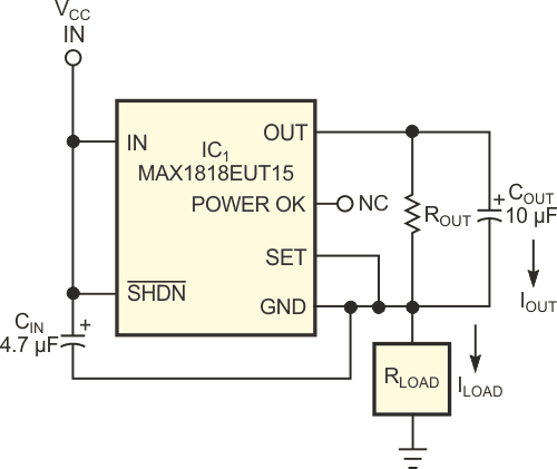
Linear voltage regulators offer a simple method of producing a constant current by connecting a fixed resistor between the regulator's output and ground nodes. The regulator's constant output voltage produces a constant current through the resistor. You can use the basic circuit as either a high-side or a low-side current source. The high-side current source uses a positive-output linear voltage regulator, IC1, a Maxim MAX1818, to provide a constant current of 25 mA to the load resistance (Figure 1). The design imposes two conditions: First, the voltage between IC1’s VCC and ground terminals must not exceed 5.5 V. Second, the voltage between IC1’s input and ground terminals must meet or exceed 2.5 V, the minimum voltage for proper operation. To satisfy these conditions, choose an output-resistance value that allows 2.5 to 5.5 V between input and ground and provides a fixed output of 1.5 V across the output resistance at the desired load current.
For example, if you use the circuit to drive a constant current through a 100 Ω maximum load resistance while applying 5 V VCC between IC1 and ground, the circuit functions properly when ROUT equals or exceeds 60 Ω. This value allows a maximum programmable current of 1.5 V/60 Ω, or 25 mA. The voltage across IC1 then equals the allowed minimum:

Available in six-pin SOT-23 packages, the MAX1818 can source as much as 500 mA.
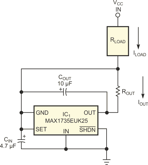
The low-side current-source circuit draws a constant current of 2.5 V divided by the output resistance through the load resistance (Figure 2). In this example, IC1, a MAX1735 linear negative-voltage regulator, provides a fixed output voltage of –2.5 V. As in Figure 1, ensuring a voltage of 2.5 to 6.5 V between IC1’s ground and input terminals represents the only precaution for its proper operation. To satisfy that condition, choose an output-resistance value that allows 2.5 to 6.5 V between ground and the input. When using the circuit to draw current through a maximum load of 100 Ω with VCC at 5 V, the output resistance should exceed 100 Ω, which provides a maximum programmable current of 2.5 V/100 Ω = 25 mA, which in turn produces a minimum recommended voltage across the device of

The MAX1735 can source as much as 200 mA and occupies a five-pin SOT-23 package.
In addition to the programmed load current, both configurations allow the regulator's quiescent current to flow through the load and introduce a source of error that varies with the voltage you apply between the regulator's input and ground connections. You can minimize the error by choosing a voltage regulator that draws low quiescent current or whose quiescent current remains constant through the operating range and allows you to compensate the error by adjusting the value of the output resistance. Quiescent currents for the devices in figure 1 and figure 2 typically average 130 µA and vary less than 40 µA for a regulator input-voltage range of 2.5 to 5 V.

