Over the years, the Design Ideas (DI) column has featured many interesting oscillators, but none that I can recall was specifically designed to produce a really clean sine wave. Putting that omission together with the need to rebuild my old sub-0.01% sine generator gave me the perfect excuse to do some exploring, ending up with this DI, which is in two parts. First, we’ll look at ways not to do it, then part 2 will show how to get Audio Precision distortion levels for RadioShack prices.
The alternatives
We won’t even consider squashing a triangle wave (Reference 1) to give something reasonably sinusoidal, as 0.3% THD is the best that this approach can give without complex, multi-breakpoint “squashing” networks. Similarly, phase-shift oscillators are out; their q-factor is low, and three-gang pots are not catalog items. And if I were designing something for modern production, the starting-point would be a 24-bit DAC fed by a small processor containing a large look-up table, but that’s not something that can be knocked up from available parts in an afternoon.
So, what’s wrong with a good old Wien bridge circuit? The relevant Wikipedia page (Reference 2) contains much historical, practical, and mathematical detail, and it reports that distortion levels down to 0.0003% (3 ppm) can be achieved, so we have one benchmark, though that’s most likely for a spot frequency rather than for a multi-range, fully-tunable device. A practical target is 96 dB or 0.0015%, which is the absolute limit for CD-type 16-bit linear PCM audio, while a more arbitrary goal is 120 dB, or 1 ppm. At these levels, THD may be dominated by circuit noise, which we’ll conveniently ignore for now.
Wien bridge oscillator
 |
|
| Figure 1. | A simple Wien bridge oscillator, using a photoconductive opto-isolator to help stabilise the amplitude. |
To check things out, I breadboarded a basic circuit using an LM4562 op-amp, carefully-matched resistors and polystyrene capacitors, and amplitude-stabilised using a photoconductive opto-isolator (essentially an LED and an LDR) driven by some heavy filtering. (A thermistor only works for higher output levels and is very bouncy.) Figure 1 shows the schematic and Figure 2 the output spectrum at close to 1 kHz for a level of –20 dBV (about –22 dBu, or 0.283 Vpk-pk).
 |
|
| Figure 2. | The spectrum of the oscillator running at ~1 kHz, its output being at –20 dBV. |
The spectrum implies a THD of about –76 dB or 0.02%: only so-so. However, I have learnt to be cautious of FFTs when the dynamic range of the signal to be examined exceeds about 90 dB, and prefer to notch out much of the fundamental, allowing a clearer view of the harmonics. Figure 3 shows the result of this: much better, with a THD of perhaps –88 dB, or 0.004%.
 |
|
| Figure 3. | The spectrum of the same signal, but with the fundamental mostly notched out to show the harmonics more accurately. |
Better, and not bad for a lash-up, but still off-target. (Note that the scale now shows the relative level of the harmonics, in dBc, as the oscillator’s output is at 20 dBV and the notch filter has a voltage gain of 10 dB or 20 dB.) With a little more thought and a lot more fiddling – or vice versa – we could probably improve its performance to the benchmark level, but a different starting-point looks more promising. The biggest problem is the amplitude control loop because removing all the ripple effects the damping badly, increasing the loop settling time. The low Q-factor of a Wien bridge, 1/3, does us no favours at all.
Bi-quad loop filter
My favorite circuit for comprehensive filters and oscillators has always been the bi-quad (ratic), state-variable, or two-integrator-loop configuration, one topology of which is shown in Figure 4.
 |
|
| Figure 4. | A classic bi-quad or two-integrator-loop filter, with its high-pass, bandpass, and low-pass outputs. |
You may well recognise something like this from a hundred and more NatSemi/TI datasheets and app notes. Its basics go back to the 1950s, I think, when “operational amplifiers” usually meant racks of glowing bottles, and it is versatile, designable, and controllable. This version is cut for a Q-factor of ~16 and a gain of ~10. We’ll now package it with a dashed line and treat it as a module. Assume ±5 V to ±15 V supplies, with plenty of decoupling caps.
To make it oscillate, we take the bandpass (BP) output and feed it back to the input at a suitable level. This is often done by limiting the BP signal with a pair of back-to-back diodes, much as shown in Figure 5.
|
|
|
| Figure 5. | The filter with added diode-limited feedback becomes an oscillator, but with plenty of harmonics, giving a THD of around 0.08%. |
With the values shown, the diodes compress the signal to ~2/3 of the output level. Less than this, and we lose stability; more, and the harmonics become excessive. The feedback network shown keeps the impedances around the diodes low to allow clean operation up to 100 kHz and beyond, while the added thermistor improves the amplitude stability with temperature. Match the diodes for forward voltage to minimize even-harmonic distortion. The third harmonic produced by the diodes is reduced by about 22 dB by the time it reaches the LP output, higher harmonics being attenuated even more.
The spectrum for the raw (LP) output shows a THD of ~0.08%, which is about the best that this approach can give. (The “notched” spectrum – not shown – showed fewer and lower peaks, but the third harmonic – the limiting factor – was still at the same level.) Because there is no control loop as such, there can be no loop stability issues, though the settling-time is appreciable at low frequencies. It’s still a good basis for a multi-range general-purpose AF oscillator.
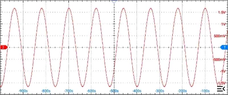
With correspondingly larger capacitors and resistors, it also works well at very low frequencies, though FET-input op-amps are needed to avoid leakage. With tuning components of 5µ7 (= 4µ7 + 1µ0; PET dielectrics) and 3M3 resistors, and with TL072s fitted in place of the LM4562s, the waveform at ~8 mHz, or a calculated 118.2 s/cycle, looks like Figure 6.
 |
|
| Figure 6. | Using µF and MΩ for tuning, a diode-stabilised bi-quad will easily work down in the mHz region – about 8 mHz, in this case. |
Why anyone would want to use a purely analog approach to generating such low-frequency signals escapes me, but trying it was irresistible, even if it took an hour or so to settle down properly. (I lacked the patience to try even larger values of timing components. And don’t even think of asking for the spectrum.)
To be continued…
In part 2, we will take the bi-quad filter and add distortion-free feedback, similar to that used with the Wien bridge but on steroids, to produce a seriously pure sine wave.
References
- Cornford, Nick. “Squashed triangles: sines, but with teeth?”
- Wien bridge oscillator