In Part 1 (Ref. 1) of this article, we briefly looked at the Wien bridge oscillator before homing in on the bi-quad filter as our best candidate for an oscillator capable of giving <0.0001%/–120 dB distortion, and showed its full circuit. Treating it as a module, it’s ready for adding distortion-free feedback in the form of a linear limiter.
Trying to use a JFET for that limiting proved disappointing. Even when the circuit was optimized to minimize its inherent non-linearity, it added about –92 dB/0.0025% of third harmonic to the feedback signal. As noted in Part 1, the attenuation of a third harmonic from the input to the low-pass output is ~22 dB, so we ended up with 0.0002% or –114 dB distortion at the output. Close, but no cigar.
Let’s return to the photoconductive opto-isolator which we used to stabilize the Wien bridge circuit in Part 1. The LDR or photo-resistor part of it is of course linear, but the LED needs careful driving to prevent any significant feed-through of ripple which would modulate the feedback and thus add distortion. Figure 1, showing the control loop added to the basic bi-quad module, incorporates a neat way of minimizing ripple while keeping reasonable loop dynamics. (That module is shown in full in Figure 4 of Part 1.)
 |
|
| Figure 1. | Using a decent control loop for the feedback stabilizes the oscillation level without adding significant distortion. |
Because the bi-quad has two outputs (HP and LP) which are in anti-phase, we can easily get full-wave rectification, but we can do much better. The BP output is at 90°/270° to those, so we can also use both that and its inverse to get 4-phase rectification, cutting the ripple to a quarter of the single-phase value. That ripple will also be at four times the fundamental frequency, so we are (roughly) sixteen times better off than we were with the Wien bridge.
With accurately-matched time constants in the bi-quad, all three outputs have identical signal levels at resonance, but any offsets or mismatches will introduce ripple as sub-harmonics of the 4× component (if that makes sense). The diodes must be well-matched, and the op-amps need to have low voltage offsets, or at least lower than any diode mismatches. Good tracking between the tuning pot sections is needed; often an extra resistor paralleled with the higher-value half gives adequate results.Good tracking between the tuning pot sections is needed; often an extra resistor paralleled with the higher-value half, equalising the sections, gives adequate results.
R16, C3, and C4 form the loop filter needed for stable operation, while R17 and C5 give extra filtering of the 4× component. These values are compromises; the loop is somewhat underdamped but gives decent performance over the entire tuning range and takes less than 500 ms to stabilize. A5 translates the filtered voltage into a current to drive the LED, thus controlling the LDR’s resistance. The opto-isolator used was a Silonex NSL-32SR3; a home-brew device made from a (recycled) NSL-19M51, a clear white T-1 LED, and thick black heatshrink worked well; though with about half the sensitivity. (I used that when experimenting with squashed tri-waves (Ref. 2), even though it wasn’t needed in the final cut.) R18 – the only adjustment needed – sets the LED drive, and thus the AF output level.
The feedback loop is closed through the network of R10, R11, and the LDR. At startup, the LDR has a high resistance, but there is enough feedback to start oscillation, after which it progressively shorts R11 to give the desired signal level.
LDRs are fairly sluggish in their response times. This one has a resistance of about 1.7k at our drive level, responding to light in ~6 ms and to dark in ~30 ms (measured 63% figures). This gives us some useful extra ripple filtering, while also affecting the control loop dynamics.
All critical op-amps are shown as LM4562s, which are my current favorites for general audio work, given their balance of low noise, distortion, and offset figures, coupled with easy availability as DIP-8s. (But what do they sound like, you say? Dunno; can’t even hear eight of them, chained between phono cartridge input and mixer output.) Their quoted THD+N of 0.00003%/–130 dB will set the limit for our performance: time to look at some results (Figure 2).
 |
|
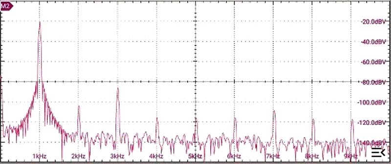
| Figure 2. | The spectrum from the low-pass output, after unity-gain buffering. |
Not very impressive! But remember from Part 1: I don’t trust my FFT if the input dynamic range is >~90+ dB, so try to remove most of the fundamental first. (Is it a coincidence that 96 dB ≈ 216:1?) Passing the signal through the – now deeper – notch filter, shows Figure 3.
 |
|
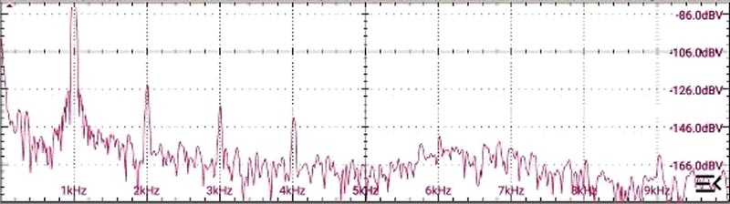
| Figure 3. | The spectrum after notching out most of the fundamental, showing the harmonics much more cleanly. |
That’s better! Note that these spectra involved very long runs, averaging the signal over tens of thousands of samples. This was needed to avoid missing valid peaks or eliminate spurious ones as well as just letting us see what would otherwise have stayed buried in noise. All tests were run with power from a 12-V accumulator – no mains hum or other nasties – with an op-amp as a rail-splitter, and in an earthed Faraday cake-tin.
I chose to use a working level of 20 dBV as being a good compromise between distortion and usability. My final unit has extra output gain, given by a virtual-earth/pseudo-log-pot stage (LM4562, of course). Figure 4 shows the notched spectrum from that, measured at +6 dBu (~+4 dBV, or ~1.54 V RMS, or ~4.4 V pk-pk), showing a THD of close to –120 dB, or 1 ppm, most of that being second harmonic (source as yet unidentified).
 |
|
| Figure 4. | Spectrum (notched) after amplification to +6 dBu. Note the altered scale. |
I think we’re there, as far as distortion goes.
Because I used sockets for A1‒A4, this being a re-build of a defunct unit, trying some other op-amps was easy. Figure 5 shows the results for the KA5532, formerly well-regarded for audio work, TL072/TL082 (or TL0n4 quad-packs), LM358 (with extra 10k resistors to Vs- tacked onto the outputs), and even the venerable MC1458 – essentially twin 741s. Frequency and output level were trimmed for each run to allow proper comparisons. The LM358 surprised me; had to double-check it. Never did like the sound of them, and now I know why.
 |
|
| Figure 5. | Distortion spectra for various other devices. |
All this work was at a nominal 1 kHz (actually 1003.4 Hz). I cannot speak for other frequencies, lacking suitable notch filters, though their un-notched spectra look much the same as that for 1 kHz, once scaled for frequency. All this work was at a nominal 1 kHz (actually 1003.4 Hz). I cannot speak for other frequencies, lacking suitable notch filters, though their un-notched spectra look much the same as that for 1 kHz. As drawn, the oscillator will tune from <500 Hz to >5 kHz in a single range, which makes it a useful bit of kit in its own right. For other ranges, the loop filters would need to be changed to maintain adequate loop stability while retaining good filtering.
These results may show THD levels below 140 dBc, or 0.00001%, or 100 ppb, but they will still be buried in noise, and the THD+N figure – which has conveniently been ignored up to now – looks much worse than the simple THD one. Calculations using the datasheet figures for the LM4562 under our conditions imply noise from the output buffer (inverting, unity-gain) of ~–114 dBV or –112 dBu in a 20 kHz bandwidth, with (resistive) Johnson noise dominant, so we may be left with a THD+N of “only” about 92 dB, or 0.0025%, or 25 ppm. An AC microvoltmeter (BW = 10 kHz) connected to the output, with R5/6 in the bi-quad disconnected and C2 shorted, measured –113 dBu, which is in line with the calculations.
Using different op-amps may help slightly with current noise, but we can never reduce the resistors’ noise unless we drastically, and unrealistically, reduce their values. Analog Devices publish a good, basic tutorial on op-amp noise (Ref. 3), as well as several much more detailed analyses. That tutorial comes from their excellent Op Amp Applications Handbook, Chapter H (for History) of which shows the intriguing route from the glowing bottles of yesteryear to the grains of refined sand that we use today.
Obviously, when using this as a source to measure the THD of an audio chain, averaging will be needed to extract the harmonics from the noise, exactly as we used throughout this DI – but make sure you can trust your FFT, or else use notch filtering to reduce the fundamental.
We now have an oscillator capable of delivering a sinewave with distortion (alone) measurable in parts per billion – OK, lots and lots of them, but hey! Who’s counting?
That sounds good – and which, given the appropriate parts, can be built in an afternoon.
References
- Cornford, Nick. “Ultra-low distortion oscillator, part 1: how not to do it.”
- Cornford, Nick. "Squashed triangles: sines, but with teeth? "
- MT-047 tutorial. Op Amp Noise
