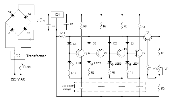
Principle and Working
The project of cell charger shown here uses IC(7808) and transistor (BC547B). The transformer TR1 is a step down transformer, and steps down 230V AC voltage to 12V AC. This 12V AC is fed to the rectifier bridge. Four IN4001 diodes constitutes the rectifier circuit. The rectifier and IC7808 together converts 12V AC to 8V DC. Transistor T1(BC547) is used as a voltage regulator. Three current selection through switch S1 can be made to select different charging current (90mA, 180mA and 300 mA). If you want to charge cell very fast, 300mA charging current should be selected, this can charge cell with-in 30 minuets. LEDs, LED1 to LED4 are charging indicator,these LEDs glows only when the cell is placed for charging. In this circuit Transistor T2, T3, T4, T5 constitutes a constant current source which charges cadmium cell.

Components Required
|
Quantity |
Description |
Value |
|
Resistors |
||
|
2 |
R1, R2 |
100 ohms |
|
4 |
R3, R5, R7, R9 |
12 ohms / 1W |
|
4 |
R4, R6, R8, R10 |
220 ohms |
|
1 |
R11 |
470 ohms |
|
Integrated circuit |
||
|
1 |
IC1 |
7808 |
|
Transistor |
||
|
1 |
T1 |
BC547 |
|
4 |
T2, T3, T4, T5 |
BD160 |
|
1 |
Transformer |
TR (0-12 /1A) |
|
Preset |
||
|
2 |
VR1, VR2 |
10K |
|
Diode |
||
|
4 |
D1, D2, D3, D4 |
|
|
4 |
D5, D6, D7, D8 |
|
|
Capacitor |
||
|
2 |
C1, C2 |
0.1uF |
|
1 |
C3 |
1000uF/ 16V |
|
Miscellaneous |
||
|
1 |
Fuse |
50 mA |
|
1 |
Cell holder |
|
|
1 |
On-Off switch |
|
|
1 |
One Pole Three Way Switch |
|
|
1 |
PCB or Breadboard |
|
|
1 |
Flexible Wire |
|
