Tony van Roon
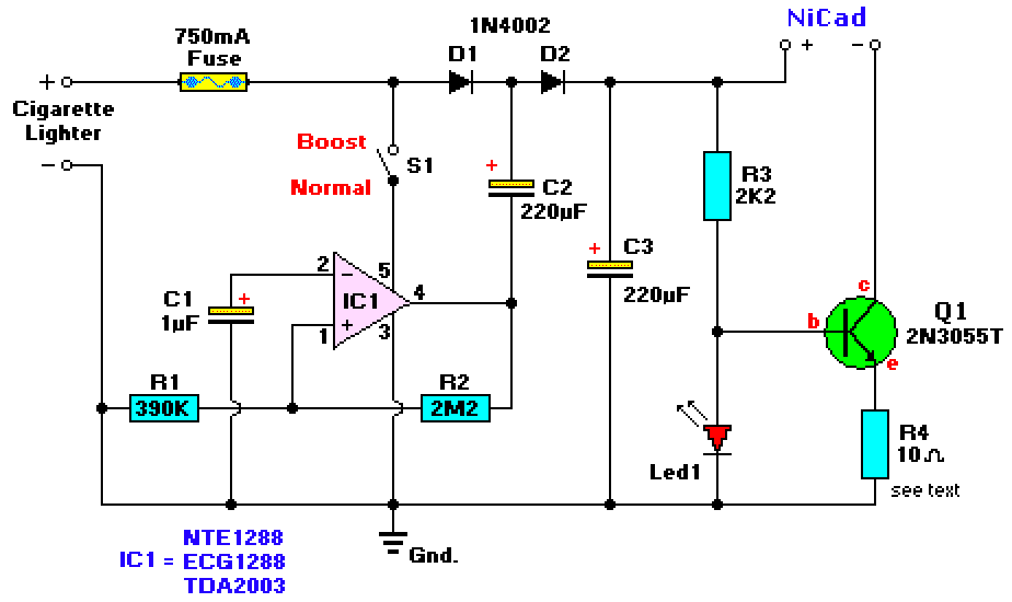
This circuit provides up to 20V output from a regular 13.2V automotive battery, to enable constant current charging of nicad battery packs up to 15 cells at 1.2V.
 |
| Car NiCad Charger circuit |
Table 1
| Part | Description | DigiKey # | Notes |
| IC1 | TDA2003, Au Amp | Pwr Amp,10A, lin, 5-pin | |
| Q1 | 2N3055T, Transistor | NPN, Power | |
| D1/D2 | 1N4002, Diode | 1N4002DICT-ND | Gen purp rect diodes |
| Led1 | Red, 5mm | Light Emitting Diode | |
| R1 | 390K, resistor | 390KQBK-ND | 5%, 1/4W, carbon |
| R2 | 2.2M, resistor | 2.2MQBK-ND | 5%, 1/4W, carbon |
| R3 | 2.2K, resistor | 2.2KQBK-ND | 5%, 1/4W, carbon |
| R4 | 10 Ohm, resistor | 10QBK-ND | 5%, 1/4W, carbon |
| C1 | 1µF, Capacitor | 25V, electrolytic | |
| C2 | 220µF, Capacitor | P5699-ND | 25V, electrolytic |
| S1 | Switch, on-off | SPST, sub-miniature | |
| Fuse | 750mA | Slow Blow |
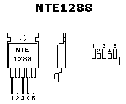
IC1 is a Linear, Audio Power Amp (10W) and was orginally designed for car radios by Toshiba. Several replacement types can be used, like the ECG1288, NTE1288 and other substitutes will work fine.
In this circuit, with S1 set in the 'boost' position, IC1 is used to form a squarewave oscillator, and by coupling this square wave to the 13.2V battery supply via D1 and D2 to obtain over 20 vdc. If this is not needed, S1 is left open (normal).
Q1 acts as a current regulator to determine the charge rate of the battery pack. Q1 should be mounted on a sufficient coolrib. R4 is selected from the table below, or it can be adapted and switched with a rotary selector switch (watch current rating!).
R4 can easily be adjusted for any value to suit your needs other than listed here.
Led1 is lights up whenever a NiCad pack is connected to the '+' and '-' output terminals.
Charge Rate Diagram
|
Cell Size |
Amp/hr Rate |
R4 Value |
|
N |
150mA |
120 ohms/0.25 W |
|
AA |
500mA |
47 ohms/0.5W |
|
C |
1500mA |
12 ohms/0.5W |
|
D |
1500mA |
12 ohms/0.5W |
|
D |
4000mA |
3.3 ohms/2W |
|
(High Capacity) |
R4 value at 14hrrate |
 |
| Pin Configuration |
