Prasad Dhond
Texas Instruments
Introduction
Sub-metering applications such as smart plugs and appliance energy meters enable consumers to understand and control their energy-usage patterns. Other sub-metering applications such as server power meters help IT departments optimize power consumption of server farms. When designing a sub-meter, considerations such as choice of sensors, analog front-end (AFE) components, and microcontrollers (MCUs) play an important role in determining the overall system cost and complexity. An effective implementation should be easy to design and low cost to mass produce while fulfilling the main requirements of the application – to reliably measure and report energy consumption information. This white paper discusses features and benefits of the MSP430AFE2xx IC [1] in energy measurement applications. While the MSP430AFE2xx is completely suitable for energy measurement in utility-grade electricity meters, this white paper specifically discusses its use in sub-metering. In the context of this white paper, sub-metering refers to non-utility electricity metering applications such as smart plugs, appliance energy meters and server power meters.
 |
|
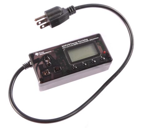
| Figure 1. | MSP430™ Energy Watchdog [2] smart plug reference design. |
Functions of a sub-meter
Sub-meters may be in the form of a smart plug (Figure 1) or they may be integrated in an appliance (Figure 2) or server. In either case, a sub-meter typically performs the following functions:
- Measures real-time energy consumption of an appliance.
- Communicates the energy consumption data to the user. This can be done with a simple LCD readout on the sub-meter itself. Alternately, the sub-meter can send the data to a remote terminal wirelessly using Wi-Fi™ or ZigBee®, or through a wired communication method such as a serial port or power line communication (PLC).
- The sub-meter may optionally have the capability to regulate power being supplied to the appliance. For example, to shut off the appliance during peak load hours or to control it from a remote location.
 |
|
| Figure 2. | Block diagram of an energy measurement system. |
Components of energy measurement
An energy measurement system requires voltage and current sensors, an AFE to interface with these sensors and an MCU to perform energy measurement calculations. The energy measurement results can be displayed on an LCD screen or sent over the serial bus to another device for wireless communication as shown in Figure 2.
Power is the product of instantaneous voltage and current. As shown in the formula below, active energy is power accumulated over time and is expressed in kilowatt-hours (kWh).

Where
VSAMP is Voltage Sample,
ISAMP is Current Sample,
N is Sample Count.
The first step in energy measurement is to measure the incoming voltage and load current using voltage and current sensors respectively.
Choosing voltage and current sensors
In sub-meters, simple resistor dividers can be used as voltage sensors. The resistor values are chosen to divide down the AC mains voltage (usually 230 VAC or 120 VAC) to fit the input range of the analog-to-digital converter (ADC). The resistor-divider circuit shown in Figure 3 can be used to divide down mains voltage of 230 VAC to around 350 mV RMS, which is 495 mV peak, before being fed to the positive input of the ADC [3]. Resistors have maximum voltage ratings, which if exceeded, can cause arcing over the body of the resistor. The use of discrete resistors (R1, R2, and R3) in series instead of a single 1M resistor allows use of standard resistors without exceeding their maximum voltage ratings. An alternate choice of voltage sensors is voltage transformers that can provide isolation from the high-voltage mains. However, voltage transformers are expensive compared with discrete resistors.
 |
|
| Figure 3. | Voltage-sensing circuit for the MSP430AFE2xx energy measurement IC. |
The choice of current sensors depends on the type of incoming mains that the appliance uses. In the U.S., appliances such as refrigerators and washing machines run on single-phase 120 VAC, whereas high-power appliances such as clothes dryers and electric cooking ranges operate on split-phase 240 VAC. For single-phase applications, a low-value shunt resistor can be placed in the neutral line (Figure 4) and the voltage drop across the shunt can be measured to calculate the current. The value of the shunt resistor is determined by the range of load currents, gain settings of the ADC and the power dissipation at the sensors. Shunt resistors are low cost and easy to use, but they do not provide electrical isolation. For appliances such as clothes dryers and cooking ranges that use a split-phase supply, current transformers must be used on each of the two live wires. Current transformers provide electrical isolation, but cost more than shunts.
 |
|
| Figure 4. | Current-sensing circuit for the MSP430AFE2xx energy measurement IC. |
The sensing stage is followed by passive interface circuitry that further conditions the input signals before being fed into the ADC. This circuitry includes a filter to remove spurious wideband noise that can lead to inaccurate measurements. For single-phase appliances such as refrigerators, two ADCs are needed: one to measure the voltage and another to measure the current. For clothes dryers and cooking ranges, four ADCs are needed to measure two voltages and two currents. ADCs with 16-bit or 24-bit resolution and simultaneous sampling capability can be used to generate accurate energy-measurement results.
Energy measurement and reporting
Energy measurement calculations are performed on the voltage and current samples collected by the ADC. As seen from the formulae below, to compute active energy, reactive energy or apparent energy, MCUs must have good math libraries for common functions such as square root, square and division.
![]()
![]()

Where
VSAMP is Voltage Sample,
ISAMP is Current Sample,
N is Sample Count.
Once energy measurement results have been calculated, they can be displayed on an LCD on the sub-meter itself or on a remote terminal. The MCU can be interfaced with LCD drivers or wireless communication modules via serial communication interfaces. If non-isolating sensors such as shunts and voltage dividers are used or if the AFE and MCU are referenced to the mains, it is critical to isolate any connection to other devices or systems that use a different reference voltage. Optocouplers or capacitive isolation ICs can be used to implement this isolation.
An energy measurement system using low-power components can be powered using a simple capacitive power supply. However, a capacitive power supply does not provide enough current to drive RF transceivers. Sub-meters that use Wi-Fi™ or ZigBee® to transmit energy consumption data will need an additional NPN output buffer or a transformer and switching-based power supply to power the RF transceivers.
Calibration
There could be differences in energy measurement values from one meter to another due to component and sensor tolerances. Electricity meters from utilities have stringent accuracy requirements and errors due to component tolerances must be calibrated out on each unit. However, sub-meters such as smart plugs and appliance energy meters typically have more relaxed accuracy requirements since their energy measurement results are not used for billing purposes. Calibration constants for a design can be determined during development and programmed in the MCU Flash memory, eliminating the need to calibrate each unit in production. It is estimated that an accuracy of <3 percent can be achieved with this approach. This accuracy is sufficient in many sub-meter applications and the elimination of calibration can result in significant cost savings in production.
MSP430AFE2xx energy measurement IC
The MSP430AFE2xx energy measurement IC (Figire 5) integrates multiple 24-bit sigma-delta ADCs, programmable gain amplifiers and a 16-bit MCU in a single package. This device is accompanied by TI’s MSP430™ MCU Energy Library [4] software to implement energy-measurement calculations.
 |
|
| Figure 5. | Features of the MSP430AFE2xx for energy-measurement applications. |
Developers will experience the following key features and benefits when using the MSP430AFE2xx energy measurement IC for sub-meters:
High level of integration
The MSP430AFE2xx integrates several components required for energy measurement including the ADCs and the MCU. This enables low-cost and small-footprint sub-meter designs that use a minimum number of components. In addition to energy measurement, the MSP430AFE2xx MCU can also be used for running other small applications as needed.
Multiple 24-bit sigma-delta ADCs
Each of the three ADCs supports a differential input voltage of ±500 mV, so outputs from the current sensor can be fed directly to the ADC without the need for level shifting. The ADC inputs also support a negative input voltage of up to –1 V which allows the divided down voltage signal from the AC mains to be also interfaced directly to the ADC without additional level shifting.
The MSP430AFE2xx offers up to three sigma-delta ADCs with 24-bit resolution. These ADCs are capable of providing utility grade (<0.1 percent) accuracy over a wide range of load currents. The simultaneous sampling feature of the ADCs eliminates inherent delay between the current and voltage samples and eliminates the need for software compensation, an anomaly of the sequential sampling approach.
Low-power consumption
Low-power consumption of the MSP430AFE2xx energy measurement IC is important in being able to use a low-cost capacitive supply to power the device.
Software programmability
The MSP430™ MCU Energy Library and sample code from TI allow quick and easy implementation of energy measurement calculations on the MSP430AFE2xx.
A key advantage of a software-programmable solution like the MSP430AFE2xx is that it provides flexibility to the system designer to tailor the solution to specific application needs. For example, the system designer can implement a non-standard communication protocol to send energy consumption data to a host processor or to a remote terminal. Another advantage of the software-programmable energy measurement IC is the possible elimination of calibration during production.
Serial communication interfaces and GPIOs
The MSP430AFE2xx allows energy-consumption data to be sent over a standard serial interface such as SPI or UART. Its additional GPIOs can be used to implement LCD interface, LED pulse generation or to interface with inputs such as keys.
Summary
Low-cost components that perform energy measurement are important in achieving widespread adoption of energy measurement in smart plugs, appliances and servers. The MSP430AFE2xx energy measurement IC includes the key components required for energy measurement, all in a single package. This includes programmable gain amplifiers, ADCs, MCU as well as serial interfaces to communicate with other devices. The MSP430AFE2xx can be interfaced with low-cost sensors such as shunt resistors and voltage dividers with only a few passive components. The ultra-low-power performance of the MSP430 family of microcontrollers allows use of a low-cost capacitive power supply to power the MSP430AFE2xx. Since this solution is software programmable, it allows flexibility to implement non-standard communication protocols. Finally, once calibration is performed during development, the same calibration constants can be programmed into each MSP430AFE2xx unit during production to easily achieve 3 percent or better accuracy. This elimination of calibration during production has the potential to significantly lower production costs.
References