LEDs are hot – in terms of market potential, if not actual temperature. As incandescent lamp bans spread around the world, LED lighting seems to have unlimited potential (see the Table 1). However, the technology has its flaws. How can we state with authority how long they will really last in service? What’s this “flicker” issue that keeps coming up? And, why are we suddenly reading about “droop” in The Wall Street Journal and The New York Times?
| Table 1. | Incandescent Lamp Limits | ||||||||||||||||||||||||||||||||||||||||||||||||||||||||||||||||||||||||||||||||||||
|
|||||||||||||||||||||||||||||||||||||||||||||||||||||||||||||||||||||||||||||||||||||
Useful Life
How long do LEDs last? If they’re properly installed and given an efficient thermal path to conduct away the heat they generate, the answer is generally a long time. The engineering question has become how long it takes for their light output to fall to some fraction of its original value (Fig. 1). Yet that isn’t totally satisfactory. A procedure that assesses “rated life” in a manner similar to the way that the rated life of conventional incandescents and fluorescents is still evolving.
 |
|
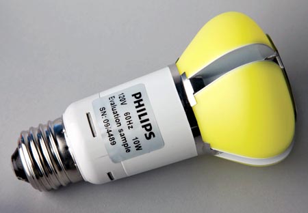
| Figure 1. | An array of Philips LED bulbs like this successfully completed 18 months of field, lab, and product testing to meet the rigorous requirements of the U.S. Department of Energy’s L Prize competition. Ironically, until last year, the LED industry had no procedure for extrapolating test data to assign actual lifetime values to specific products. |
Last August, the Illuminating Engineering Society of North America (IESNA) released IES TM-21-11: “Projecting Long Term Lumen Maintenance of LED Light Sources.” [1] The document describes how to take data that was already being measured by an approved process and extrapolate it.
However, TM-21 only applies to specific light source components (package, module, array), not an entire luminaire. A complete luminaire is a complex system with many other components that can affect lifetime such as the driver, optics, thermal management, and housing. The failure of any one of these components can mean the end of the luminaire’s useful life, even if the LEDs are still going strong. Any meaningful projection of lifetime must account for all of these components and not simply focus on the LEDs.
When incandescent and fluorescent light bulbs are evaluated, a large and statistically significant sample is operated until 50% have failed. That point, in terms of operating hours, defines the rated life for those lamps. [2] That doesn’t work for LEDs, which typically don’t fail abruptly. Instead, their light output slowly diminishes over time.
Also, that notion about LEDs lasting “a long time” means that acquiring real application data on long-term reliability becomes time-challenging. Moreover, the light output and useful life of individual LEDs tend to be influenced more by how much current they’re driven by and how hot they get in the luminaire where they’re mounted.
Lumen Maintenance Life And Rated Life
Before explaining how TM-21 is applied, it will be useful to distinguish between maintenance life, which TM-21 addresses, and rated life, which relies on a procedure that doesn’t have the same authority as TM-21 yet. Again, rated life is used to assess conventional lamps.
Conceptually, the value of lumen maintenance (Lp) derived from test data by TM-21 describes the number of hours of operation over which the LED light source will maintain a certain percentage, p, of its initial light output. For example, L70 would be the number of hours until an LED’s light output had decayed to 70% of what it was when the LED was new.
For the last several years, the industry has used a test procedure described in IESNA as LM-80-8 to measure Lp for LED packages, arrays, or modules driven by auxiliary drivers. [3] In the LM-80 procedure, LEDs are driven with external current sources. Their case temperature is controlled during operation, with measurements made at room temperature.
In more detail, the devices under test are operated at three case temperatures: 55 °C, 85 °C, and one other temperature selected by the manufacturer. Air temperature must be maintained to within ±5 °C and case temperature to within ±2 °C. Relative humidity must be less than 65%.
This environment is maintained for a minimum of 6000 hours (roughly 38 weeks). Data is collected every 1000 hours. The data collected comprises lumen output, changes in chromaticity (color), and any incidents of catastrophic failure (burnouts).
“B” specs add a target statistical confidence interval. Thus, B50 indicates that no more than 50% of a sample of LED devices would be expected to have their light output drop below a target lumen maintenance level. B10 would mean no more than 10% of the sample met that L standard within the given time.
Limits Of LM-80
LM-80 is a test procedure only. Deliberately, it does not include a way of getting from those recorded test results to any values of Lp for the devices under test. After the industry agreed on LM-80, it still needed pass/fail criteria, or a way of graphing results so people could make sense of the data. No curve-fitting methods were recommended for extrapolating from the data to predict L70 values.
Sample sizes and the values or even the number of drive currents were left up to whoever created any particular test. There was even a problem with determining what kinds of LEDs the data applied to, because there were no criteria for what LED package changes would require new testing.
This was particularly critical because the industry is constantly innovating packaging to improve the heat-flow characteristics of the devices. Because LEDs do not shed heat by radiation, like incandescent lights, the effectiveness of packaging in providing a thermal path from the LED junction to heatsinks and the ambient environment can have significant effects on Lp.
Some of these issues were addressed early. The U.S. Environmental Protection Agency (EPA) introduced some standardization for testing residential and non-residential indoor and outdoor lamps. It required LM-80 testing be conducted by labs accredited by the National Institute of Standards and Technology’s (NIST’s) National Voluntary Laboratory Accreditation Program (NVLAP).
For each combination of current and external temperature, the EPA required a minimum of 25 samples. To pass, after 6000 hours, the value for LM had to be better than 91.8% for products intended for residential indoor use or better than 94.1% for non-residential and residential outdoor use. That clarified some points, but everybody was waiting for IESNA TM-21.
TM-21 Details
The new document specifies precisely how to extrapolate the LM-80-08 lumen maintenance data (Fig. 2). Here’s how it works:
- For each unit in the data set, the measured light output at the start of is normalized to a value of “1.”
- At each point where light output is measured, the normalized data for all units is averaged. (In other words, the results depict the average behavior of the whole set of units.)
- All data from the start of the test to 1000 hours is discarded.
- If the test stops at 6000 hours, the average lumen maintenance data points from 1000 hours to 6000 hours are fit to a simple exponential extrapolation model using a least-squares curve fit.
- If the test runs for 6000 to 10,000 hours, only the last 5000 hours of data are used for the extrapolation.
- For tests that run more than 10,000 hours, the data points from the last 50% of the total measurement time are used. However, if the last 50% of the total measurement time is not an integer multiple of 1000 hours, take more than 50% until the data comes out to an integral multiple of 1000 hours. The “times-six” rule is intended to limit the length of lumen maintenance predictions.
 |
|
| Figure 2. | The extrapolation process described in IES TM-21-11, “Projecting Long Term Lumen Maintenance of LED Light Sources,” provides a bridge from LM-80 test results to predictions of lumen maintenance. |
If that description is too concise to really understand, don’t worry. In January, the EPA made available the Energy Star TM-21 calculator. [4] Its availability makes it possible for users to request LM-80 data sets from LED vendors and interpolate (for example) from test values at 55 °C and 85 °C to obtain lumen depreciation values for 75 °C.
Rated Life
The best reference for understanding the difference between TM-21 lumen-maintenance life and rated life is an article by Jianzhong Jiao of Osram Opto Semiconductors in LEDs Magazine, “Understanding the Difference between LED Rated Life and Lumen-Maintenance Life.” [5]
To explain the difference, Jiao refers readers to ANSI/IES RP-16, which describes the process for consistently determining the life value for conventional lamp types. In RP-16, rated life is designated Bp and expressed in hours, where p is a percentage. Thus, a B50 of 1000 hours means that 50% of the tested products lasted 1000 hours without failure.
B50 is also known as the products’ rated average life. For example, if a product has a B10 rated life of 1000 hours, 10% of the tested products failed within 1000 hours and could be compared favorably to a product with a B50 rated life of 1000 hours. “While Bp life is a statistical measure, Lp life is a defined durability measure,” Jiao says.
Bp life testing, then, requires a large and statistically meaningful sample size. There is no similar requirement for Lp life testing. The catch, Jiao notes, is that when LM-80 test data is used to make lumen-maintenance projections per TM-21, the sample size will affect the uncertainty of the projection. Consequently, a smaller sample size will lead to shorter projected life to increase the statistical certainty.
With that caveat in mind, the first thing that must be defined to provide a sensible basis for LED rated life estimates is what constitutes a “failure” of an LED that has lost luminance but hasn’t burned out.
For example, Jiao says, “failure might be defined as when the light output of an LED reaches 70% or lower of the initial light output (including if the LED’s light output is zero). In other words, for a given period of time, if an LED produces insufficient light or no light, the LED is considered at failure.”
That would make it possible to combine a new statistical measure with the defined durability measure. Jiao suggests this would be a BpLp value. If an LED light source claimed to have B50L70 of 30,000 hours, “then 50% of tested samples should have a lumen-maintenance life of 30,000 hours,” Jiao says.
To support that, Jiao recommends integrating the statistical failure measurement with lumen-maintenance measurements during the life test. This would require a large enough LED sample size to be statistically meaningful, as well as additional tracking and recording of sample behaviors. A key point is how long the testing would continue.
Instead of stopping at some arbitrary multiple of 1000 hours, “when 50% of the tested samples reached a light output equal to 70% of initial lumens, including the samples that failed to produce light, then B50L70 (in hours) [would be] obtained,” Jiao says.
Jiao acknowledges a practical problem with that. It’s reasonable to expect B50L70 values to turn out to be on the order of 30,000 hours, so we really need a way to make a projection based on shorter testing periods. Fortunately, LED makers have already figured much of this out. They have taken two approaches.
One approach carries out LM-80 testing on large samples recording both light-output changes and failures. The data is then fitted into a mathematical model with a statistical-certainty band. By analyzing the lumen-maintenance projection curve along with the associated sample distribution bandwidth, it’s possible to project an estimated B50L70 life.
Alternatively, manufacturers have always tested for real failures (the light goes out) separately from official LM-80 testing. Infant mortality is fundamentally a manufacturing-process problem, and process control is a key to profits.
What’s needed is a way to combine the data from both types of testing in a way that everybody agrees is fair. Then, using TM-21, the lumen-maintenance projection can be established, and the data collected in the accelerated-failure-modes test could be modeled with a different mathematical expression, with the rated life projected by mathematically combining both models.
That’s Jiao’s and Osram’s recommendation. Before the industry establishes a recommendation for a standard practice, though, LED integrators may need to request more testing and modeling information from the manufacturers in regards to the statistical failures of LED light sources.
Flicker
The light output of devices driven by ac can flicker at twice the line frequency, at harmonics of that frequency, and sometimes at the fundamental of the line frequency. Flicker generally isn’t observed in incandescent bulbs because of their thermal inertia.
However, flicker can be observed with fluorescent tubes and with cold cathode fluorescent lamp (CCFL) and LED backlighting of video displays. Medical research associates flicker with symptoms of migraine and epilepsy in a segment of the population.
For LEDs, the solution is to clean up the output stages of driver circuits. Scott Brown, senior vice president of marketing at iWatt, believes upcoming European regulations might become part of IEC 61000-3-2, the European standard for power-factor correction (PFC) in AC-DC supplies.
Brown agrees with Matt Reynolds, applications manager for solid-state lighting at Texas Instruments’ Silicon Valley Analog Division (the former National Semiconductor), and Suresh Hariharan, applications director at Maxim Integrated Products – there is something serious behind the issue, though the problem can (and should) be dealt with at a small cost delta.
Hariharan says flicker comes down to legacy triac dimmers and the way LED drivers turn their chopped ac cycles into the pulse-modulated DC that regulates the light output of the device. A properly designed dimmable driver, all three companies agree, has three stages: an AC-DC stage and two DC stages, the final one of which pulse-modulates the current to control light output.
“Proper design” also demands power-factor correction (PFC) in the AC-DC stage to keep the harmonics of the AC line frequency off the power lines. [6] Yet not all dimmer-compatible drivers provide PFC, Hariharan says.
Plenty of companies around the world make generic LED “light bulbs.” The driver electronics all fit into the base of the bulb, so nobody knows whose electronics are in there. If a copycat company wants to save a few cents on the bill-of-materials and use a cheaper driver chip, who can tell?
Also, the cheaper drivers might not display any flicker. That’s because the triac in the dimmer in the wall of the building is often the element where the problem starts. If the triac switches ON at a different point in the first half-cycle of the AC waveform than it does in the second half-cycle, a series of harmonics is produced that (among other things) shows up as flicker at the AC line frequency.
What to do about that depends on the driver design. But the ultimate solution, Hariharan believes, is more expensive DC circuitry in the delivery stage. Encouraging this requires a standards-based approach. That may be the IEC in Europe or the IEEE in North America.
Enter The IEEE
This is where IEEE Projects Authorization Request PAR 1789 enters the picture. The standards body is working on P1789, tentatively titled “Recommended Practices of Modulating Current in High Brightness LEDs for Mitigating Health Risks to Viewers.”
The first of the group’s efforts has been released for public comment. [7] The report has been out for more than a year, so there’s no urgency. But that doesn’t mean the document is uninteresting. It includes detailed references to and summaries of multiple studies of the effects of flicker on humans who are exposed to it through fluorescent lighting.
For instance, photosensitive epilepsy is more common than one might think, affecting “about one in 4000 individuals,” according to the group. Factors that may combine to affect the likelihood of seizures include flash frequency in the range of 3 to 65 Hz, and especially in the range from 15 to 20 Hz. That’s why line frequency fundamentals (50 or 60 Hz, depending on country) are important and why asymmetric behavior of the external triac controller is significant.
“Deep red flicker and alternating red and blue flashes may be particularly hazardous,” the group notes. “Bright flicker can be more hazardous when the eyes are closed, partly because the entire retina is then stimulated.”
Droop
“Droop” refers to the phenomenon in LEDs where more current produces more lumens of output only up to a point, beyond which lumen output no longer increases linearly with increasing current (Fig. 3). This phenomenon in LEDs has always been hard to explain.
 |
|
| Figure 3. | With conventional LEDs, light output does not increase linearly with current. Something happens with the recombination of election-hole pairs that normally results in the emission of a photon. A phenomenon called auger scattering, in which an electron is generated instead of a photon, is presently considered the best candidate for an explanation. This is leading at least one company to pursue GaN-on-GaN as a possible solution. |
The quantum process by which the generation and recombination of electron-hole pairs causes photon emission doesn’t behave nicely. Beyond a certain current, the recombinations apparently produce another electron, instead of a photon.
Semiconductor physicists who deal with LEDs have been chasing several suspect processes because knowing which one it is could provide a handle for dealing with droop. The prime candidate today is Auger scattering, named after Pierre Victor Auger, a twentieth century French physicist.
The droop issue came to the forefront in February when Soraa, the LED startup founded by Shuji Nakamura, the inventor of the blue laser and LED, described the company’s GaN-on-GaN (gallium nitride) LEDs at the Strategies in Light show. According to Soraa, its LED material is 1000 times freer of dislocations than the usual silicon carbide. Also, its LEDs can be driven much harder (250 A/cm2) than traditional LEDs without exhibiting significant droop.
At the same time, Soraa made a full-court press with the business media, including The New York Times and The Wall Street Journal, but did not engage the technical trade press or issue a press release about product availability or pricing. GaN-on-GaN bears watching, given Soraa’s intellectual property (IP) portfolio and technology team, but it’s too soon to speculate about where in the lighting spectrum it will fit.
References
- IES TM-21-11: “Projecting Long Term Lumen Maintenance of LED Light Sources”
- Don Tuite, “High Brightness White LEDS Light The Way To Greener Illumination”
- Another test, LM-79, is an approved method for taking electrical and photometric measurements of solid-state lighting (SSL) products. It covers total flux, electrical power, efficacy, chromaticity, and intensity distribution and applies to LED-based products that incorporate control electronics and heatsinks, including integrated LED products and complete luminaires, but not to bare LED packages and modules, nor to fixtures designed for LED products but sold without a light source. Unlike traditional photometric evaluation, which involves separate testing of lamps and luminaires, LM-79 tests the complete LED luminaire because of the critical interactive thermal effects. While LM-79 doesn’t address product reliability or life, it does provide for the important calculation of complete luminaire initial efficacy.
- The EPA’s Energy Star TM-21 calculator can be downloaded at energystar.gov/TM-21calculator.
- “Understanding the Difference between Led Rated Life and Lumen-Maintenance Life”
- Jianzhing Jiao, “What’s The Difference Between Reactive Power Factor And AC-DC Supply Power Factor?”
- “A Review of the Literature on Light Flicker: Ergonomics, Biological Attributes, Potential Health Effects, and Methods in Which Some LED Lighting May Introduce Flicker”