Mike Szczys
hackaday.com
Microchip has unveiled a new dev board called the Curiosity Development Board. I had my first look at this at Bay Area Maker Faire back in May but was asked not to publicize the hardware since it wasn’t officially released yet. Yesterday I got my hands on one of the first “pilot program” demo units and spent some time working with it.
I requested a sample board out of my own curiosity. As you may know, Microchip is one of the sponsors of the 2015 Hackaday Prize, but that partnership does not include this review. However, since we do have this relationship we asked if they would throw in a few extra boards that we could give away and they obliged. More about that at the end of the post.
Overview
I haven’t really done any PIC development. I started off with Atmel chips because you could program them with a parallel port. These were the pre-Arduino days and I didn’t want to invest in a proper programmer until making sure I liked the chip family. This could not be done at the time with Microchip microcontrollers – or at least bootstrapping a programmer was harder – since they needed a 12 V source when programming. That “high voltage” signal was provided by a PICkit or similar programmer. I think the Curiosity is a great way around this issue. It uses PKOB – PICkit on board – for both programming and debugging.
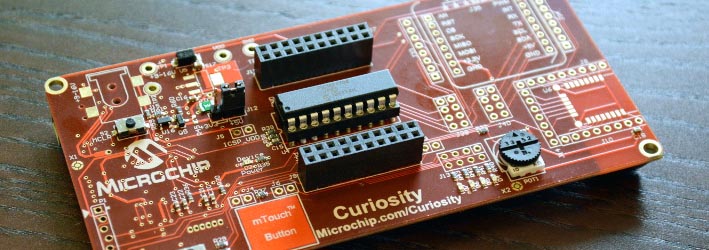
Curiosity has a DIP socket in the middle of the board with pin breakouts to either side. The board has a programmer/debugger built into it which means just add a USB cable and computer and you’re up and running. The setup reminds me of TI’s MSP430 Launchpad board, and I really like that one.
The machined pin header plays host to 8, 14, or 20 pin chips from the PIC12, PIC16, and PIC18 families of 8-bit processors. The early version I received shipped with a PIC16F1708 but I’m told that production versions will ship with the PIC16F1619. If that’s not the chip you’re looking for they do have a sample request button for each chip listed on the “supported devices” tab of the Curiosity page. The ability to try out a bunch of different 8-bit chips and swap them out on this board is a perfect way to get your feet wet.
Delving into the details
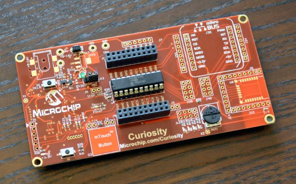
My board has four rubber feet on the bottom to sit nicely on the bench (and keep the bottom side away from stray leads and other conductive detritus). For user input there is a single button, a capacitive touch button, and a potentiometer. The placement of the user button and the foot underneath is dubious. Since the button is to the outside of the foot, pressing the button tilts the whole board if you don’t hold down the opposite corner. I asked about this and Microchip had the same issue in their testing. The production boards will ship with standoffs installed at the four corners (metal for the first 500 boards and probably plastic standoffs at scale). It’s nice to see they’re working to cover all bases before these hit the public.
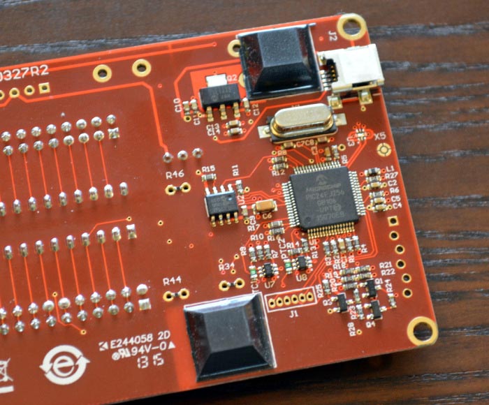 |
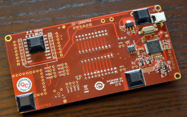
| PKOB programmer/debugger on bottom side of board. |
|
| Top footprints for mikroBUS and BTLE module. |
The corners of the board are rounded and the edges are the smoothest I’ve ever felt on a dev board. Real estate to the left of the chip and breakout headers is used by the programmer/debugger circuit located on the underside of the board, with a foot print on the top side to add an optional barrel jack for 9 V input (this will be regulated by existing parts). There are also a pair of headers for connecting a bench supply that performs its own regulation.
To the right on the top of the board there are two footprints for add-on hardware. One is a dedicated design for the RN4020 BTLE module. The other footprint uses the mikroBUS pinout standard. I’ve heard the name before but this is the first time I’ve looked into it. A few of the Hackaday crew have seen the standard in action and mention that it is more popular with engineers in Europe. At the least, it’s a set of SIL outlines spaced at a multiple of 0.1″ so you can plug the modules into a breadboard (unlike the Arduino shield standard). At it’s best, Microchip is embracing a standard that has been around for more than a few years rather than try to invent their own. It’s well documented so you can build your own modules or use those already on the market from many different companies.
Perhaps the finest part of this design is the lengths that they’ve gone to in order to make all pins available. Every place that pins have been routed to function-specific footprints (mikroBus, user button, LEDs, capacitive pad, but not the BTLE header) there is an easy way to get at the signals.
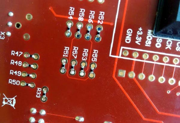
Next picture is a close-up of the bottom of the board. You can see there are DIL headers where pads from each row are connected together with zero Ohm resistors. Snip or desolder these jumper resistors and you disconnect the component. It’s better than cutting traces on the board because you can populate the footprint with pin headers and use jumpers to patch back in the original functionality. Nice, huh?
Programming experience
I downloaded and set up the MPLABX IDE. Kudos to Microchip for having a Linux version (if only Cypress could do the same for PSOC4!). After opening the sample code from the Curiosity page I chose the included compiler and selected the programmer type and was unable to build the examples. Reading through the Curiosity User Guide (PDF) I discovered that I needed to download and install the free version of the XC8 compiler. After that I had no problem building and flashing the examples. The first time around the IDE even did an automatic firmware upgrade to the PKOB programmer. This is definitely one of the easier toolchain setups I’ve gone through.
Generally I avoid proprietary toolchains (I also have the luxury of not making a living by building electronics so a bit of hassle is not big deal). I did some quick searching and I don’t think you can use the SDCC Open Source Compiler for this particular chip (PIC16F1708) but there are other chips supported by that compiler and I don’t see why this programmer wouldn’t work with Open Source programming tools as well. I just didn’t have the time to test before publishing this article.
Conclusion
This is a well-conceived and well-designed development board. The ability to swap out chips, and the additional breakout footprints providing access to IO pins makes this one of the most flexible dev boards of any architecture. I enjoy minimalistic “bells and whistles” so the inclusion of one button and four LEDs hit the sweet spot for me. At $20 MSRP this is a safe bet for those not wanting to take the $50 plunge on a standalone PICkit 3 programmer. Having both programming and debugging options means this will be a tool that is hard to outgrow.