Aaron Hanson
allaboutcircuits.com
Learn about the RN487x family of Bluetooth modules and how to configure them for your low-power peripheral projects.
If you are developing a small, low-power peripheral, the odds are good that you are considering Bluetooth as your communication layer.
As the standard has evolved, Bluetooth-connected devices have proliferated. Hardware modules have been introduced that provide a complete SoC (system on chip) for almost any peripheral design. The Nordic NRF52840 is a good example. The system core is a 32-bit processor and multi-protocol Bluetooth radio. This core is surrounded by every interface you might need; GPIO, PWM, USB, SPI, I2S, and many more.
The downside to this powerful SoC, and others, is complexity. There is a significant learning curve and development time required to create and integrate the necessary embedded software for these SoCs.
For some of the most common types of peripherals, however, there are simpler alternatives. If your peripheral is primarily a remote sensor or a remote control, with a limited number of channels (analog and digital), you can probably meet your goals with the RN487x module manufactured by Microchip.
This family of two Bluetooth modules provides multiple, concurrent, bi-directional digital and analog channels. The module is tailored to specific designs just by storing a little bit of configuration in the module NVRAM. Despite the simplicity, the module still conforms to the BLE (Bluetooth low-energy) standard, so it is compatible with the newest Bluetooth clients, such as modern smartphones.
In this series, we will demonstrate using the RN487x module. We will create a functional Bluetooth-connected peripheral for each of the four tasks; a digital sensor, a digital control, an analog sensor, and an analog control. Each example includes a nominal circuit, and the configuration necessary on the RN487x. A simple application script for exercising the peripheral is also provided. The interface points in the application script are well documented; maximizing the potential to incorporate these peripherals as subsystems in larger designs.
Design Overview
Let’s look at a graphical breakdown for the ‘analog sensor’ example, with key interfaces in red (Figure 1).
 |
||
| Figure 1. | Graphical representation of a Linux system communicating with a peripheral. | |
There are three system elements that we will create. For the peripheral, we must create hardware that provides our sensor signal; the transducer in this example. It generates a varying analog voltage. For the user, we will create an application to present the data; the Python script in this example.
The script must use the GATT API to transfer information to and from the peripheral. We will also need to create some configuration in the RN487x module. This configuration will control the flow of data between the application and the hardware.
Component Selection
There are two modules in the RN487x family; the RN4870 (Figure 2) and the RN4871 (Figure 3). They differ in the number and type of pins provided for I/O. You can find these constraints in the datasheet [1] and user guide [2], but it is somewhat scattered. Below is a reorganization of the pin budget for the two chips (Table 2, 3). This arrangement should make it easier to see which chip you need for your peripheral.
There are three I/O pin types available on the RN487x modules (Table 1):
| Table 1. | Pin types available on the RN487x modules. | ||||||||
|
|||||||||
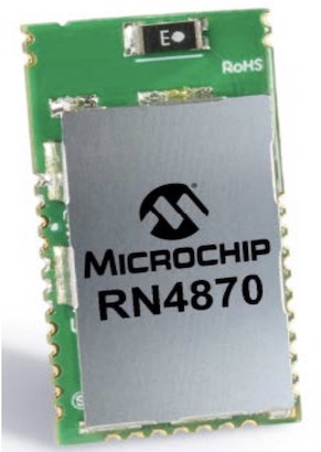 |
||
| Figure 2. | Microchip RN4870 Bluetooth Module. | |
| Table 2. | Pin budgets for the RN4870 Bluetooth module. | ||||||||||||||||||||||||||||||||||||
|
|||||||||||||||||||||||||||||||||||||
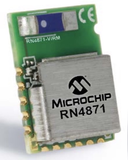 |
||
| Figure 3. | Microchip RN4871 Bluetooth Module. | |
| Table 3. | Pin budgets for the RN4871 Bluetooth module. | ||||||||||||
|
|||||||||||||
These tables should make it clear that if you do not need PWM, and you only need to manage one or two signals, use the 4871. This will save resources. If you need PWM, or if you want to manage more than two signals, then you need the 4870. For our analog sensor, we have only one analog input so the 4871 would be sufficient. We would connect the signal to the P1_2 pin of the module.
GATT (Generic Attribute) Profile Layer of the BLE Protocol Stack
We’re almost ready to implement some real examples. But in order to write the user application, we need a more precise understanding of the api we will use when we talk to the peripheral.
All Bluetooth Low Energy devices use the Generic Attribute (GATT) Profile for exchange of structured data. In this model, the peripheral is organized as a server that holds a simple database. The database in turn holds a number of variables that represent the useful data. Applications such as our Python script are organized as clients that use the GATT API to make name-based queries into the database. The API can be used to read values from the database, and to write values into the database[3, 4].
As a preview, here are two useful GATT API method calls in Python[5]:
gatt_rq.connect()
gatt_rq.write_by_handle(vh_light, str(bytearray([8]))
The first is used to establish a connection to the peripheral. The second writes some values to the database; these values are immediately expressed as digital outputs on the peripheral. The first argument to the ‘write’ method is a handle that is specific to the digital output or outputs we want to control. There are just a few more lines necessary for a functionally complete example.
This API is exposed as part of Bluetooth services in iOS, Android, Windows, and Linux. The examples in this article are written in Python, and will run in many common Linux distributions[5].
Module Configuration
The ‘vh_handle’ parameter in the script method above leads us to the final element in this design pattern. The parameter is a reference in the software for a specific physical-level signal on the peripheral. But how is this data path completed? There are two pieces of configuration in the NVRAM of the RN487x that will do this; characteristic definition and pin binding.
- Characteristic definition: Commands that allocate space for values in the database, and that give each value a unique identifier for reference by client applications.
- Pin binding: Scripts that transform physical signals into database values, and vice-versa.
RN487x configuration is loaded into the module with a custom command language. See Part 2 for a general guide on making a console connection to the module, and on issuing configuration commands.
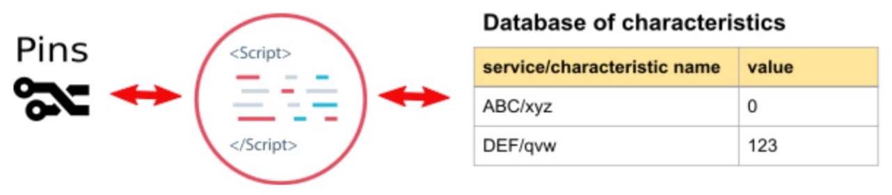
After we’ve issued these commands, the non-volatile configuration within the RN487x will look something like this (Figure 4):
 |
||
| Figure 4. | The non-volatile configuration organization within the RN487x after configuration is loaded into the module. | |
Note that all the data values exist within a two-level hierarchy of ‘services’ and ‘characteristics’. This organization is more than we need, but becomes useful for complex systems where multiple sensors and controls would exist within logically separate services.
This concludes part one of our four-part series on the RN487x module. Parts 3 and 4 will utilize the same design pattern to create a digital input, a digital control, an analog sensor, and an analog control.
