Hold the current constant and within tolerance.
Steve Sheard, ON Semiconductor, Tempe, AZ
LEDs are more efficient than incandescent lights and can last 100 times longer, but they require specialized electronic-drive circuits to avoid overstress conditions. The main operating parameter is relatively simple: Keep the current through the LEDs constant and under the specified maximum.
Traditional power supplies have accurate voltage outputs with variations in current. A resistor in series with an LED string controls the current. Such a design assumes a known voltage across the LEDs that does not vary with changes in LED temperature. Unfortunately, LEDs’ forward voltage does change with temperature. LED manufacturers generally bin their devices by forward voltage, allowing a lighting manufacturer to build a lighting fixture to match this forward voltage at a fixed temperature. A circuit using unbinned LEDs saves the LED manufacturer time and results in less expensive LEDs. LEDs also have a negative forward-voltage-to-temperature coefficient that can cause the drive circuit to go into thermal runaway, requiring the designer to build safeguards into the design.
The ideal approach for driving LEDs is one in which the circuit monitors the current and keeps it constant. LEDs’ forward voltage does not affect this type of circuit, eliminating the need for binning and the effect of the LEDs’ negative forward-voltage-to-temperature coefficient. These circuits can be complex switching regulators or simple linear regulators with feedback loops. Complex switching regulators are ideal for high-light-output applications, such as streetlights.
Simple, economical, and robust hybrid circuits find use in architectural- and interior-lighting fixtures. These circuits’ design may be less efficient than that of a complex switching regulator, but their low cost and simplicity make them attractive. These circuits operate over the full universal voltage specification of 85 to 265V ac at 50 or 60 Hz.
The circuit in Figure 1 comprises a bridge, a chopper, and a current regulator. The full-wave bridge comprising diodes D1, D2, D3, and D4, feeds into the chopper circuit. MOSFET Q2 immediately turns on, and capacitor C1 begins to charge.
 |
|
| Figure 1. | This circuits drives a string of LED with a constant current over the entire wordwide range of ac-mains voltages. |
Resistors R1 and R2 form a voltage divider. When the voltage on the cathode of D5 reaches 43.5V, the zener diode conducts and turns on Q1, which pulls the gate of Q2 low, causing it to turn off. Diode D6 protects Q2’s gate.
The voltage across C1 stays at 80 to 90V. The charge on C1 feeds the CCR (constant-current regulator) and the LED string. This circuit example has 22 LEDs. The CCR maintains the current at 20 mA through the LED string. The circuit includes resistor R4, in series with the LEDs, for measuring the current through the LED string.
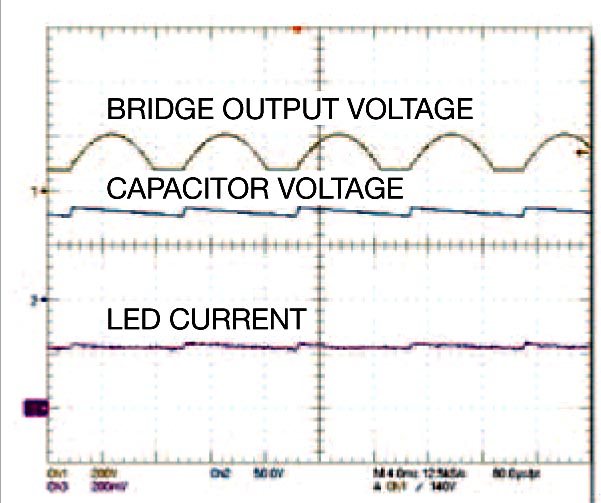
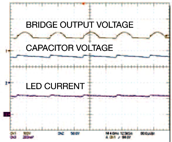
Figure 2 shows the voltages at different parts of the cycle with an input voltage of 150V ac. Trace 1 is the output of the bridge-rectifier circuit. Trace 2 is the voltage across C1, the output of the chopper circuit. Trace 3 is the voltage across the current-sense resistor. The traces clearly show that, when the voltage from the bridge increases to more than 80V, the chopper circuit switches and limits the voltage applied to the regulator circuit. Figure 3 shows the voltages with an input voltage of 85V ac.
 |
 |
|||
| Figure 2. | When the voltage from the bridge increases to more than 80V, the chopper circuit switches and limits the voltage applied to the regulator circuit. | Figure 3. | At 85V AC, the circuit continues to operate by keeping Q1 on for a longer period. | |
The oscilloscope traces show that there is still sufficient design head room, with Q1 staying on for a longer period, during which C1 fully charges. The input voltage drops to 54V ac before the current through the LEDs begins to drop.
 |
|
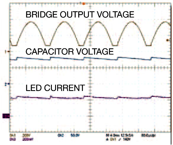
| Figure 4. | At 265V AC, the circuit has enough energy to keep C1 charged during off cycles. |
Figure 4 shows the circuit operation at an input voltage of 265V ac. Trace 1 shows that, because of its high input voltage, Q1 is on for a short time. Trace 2, however, shows that sufficient energy still remains to charge Q1 and maintain the current through the LEDs during the off cycle.
You can scale this circuit to operate with different LED arrays. CCRs are available with current ratings as high as 160 mA. For higher currents, you can place the CCRs in parallel. The values of C1, R1, and R2 match the type and number of LEDs.
