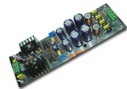
This is a precision ±15V regulator on a single side PCB. The circuit is based on EB-802 with design by zerosoft on www.headphoneamp.co.kr . I have replaced some components that easy to find in the market and design a new PCB that look like symmetry layout. But, you can replace the components with high quality component if you can find.

Prototype the top layer of PCB I use as ground plane only and unnecessary becuase all importance PCB route is the bottom only.
Adjust VR1 and VR2 to achieve the desired voltage output (±15V at CON2).
Schematic
PCB
Components
|
D1-D4
|
1N5822
|
|
C1-C4, C13, C14, C19, C20
|
0.1uF/63V flim capacitor
|
|
C11, C12
|
220uF/16V
|
|
C15, C16
|
47uF/35V
|
|
C5-C10
|
2200uF/25V or 35V Electrolytic capacitor
(C7 and C10 may be 1000uF/25V) |
|
L1 and L2
|
100uH
|
|
Q1
|
IRF640 N-channel MOSFET
|
|
Q2
|
IRF9640 P-channel MOSFET
|
|
IC1 and IC2
|
NE5534 OP-Amp
|
|
D9 and D10
|
LM326-5.0 Voltage reference or LM329DZ/6.9V
|
|
Ttransformer
|
15-0-15 V, 2A
|
|
All resistors are Vishey/Dale RN-55
|
|


