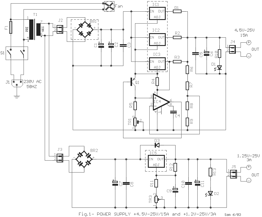
The circuit is based on application of National Semiconductor. First is constituted by three voltage regulators LM338 [IC1-2-3] connected `'in parallel' '. The each one regulator has the possibility of giving 5 A in his output. Also exists the possibility to regulate the output voltage from +4.5 V until 25 V DC, stabilized. The voltage regulation in the output becomes with the TR1. If it does not exist the need of this continuous output voltage regulation, then we can measure the resistance value of trimmer TR1 in the particular output voltage and him replace with proportional value constant resistance.

The Rectifier Bridge BR1 should be placed in some point of metal box so that it's frozen. On the contrary the IC1-2-3, that good are is TO-3 case, should be placed in a capable dimensions heatsink, with suitably mica isolation between them and the heatsink. Also it should sort-circuit in no point with heatsink. Resistors R1-2-3 should be placed in some distance from the PCB in which make the circuit, because are hot and exists the danger to burn the printed board in that point. A point that should it's given attention they are the cables from where it passes big current, it's big diameter, as well and the output plug of suitable type and carefully placed so that does not exist the case of short-circuit. In the second part of drawing exists a simpler circuit that is based on the voltage regulator LM350 which has the possibility of giving in the exit regulated voltage from +1.25 V until 25 V Dc and biggest current 3 A. Good is the IC5 are in case the TO-3 for better thermic conduct and it's placed on heatsink [with essential mica between this and heatsink]. The voltage regulation in the output becomes with the trimmer TR2. All the circuit is supplied from power transformer bigger than 450VA. The manufacture of circuit should become in suitable dimension box that should ventilate well. In the expulsion of temperature can help a fan 12X12cm working in 230Vac. In the outputs you can place Voltmeter and Ampermeter.
| R1-2-3=0.1R 5W | C3-5-8-10=100nF 100V MKT | IC1-2-3=LM338 [TO-3 case] on Heatsink |
| R4=100R 0.5W | C4=220pF 100V ceramic | IC4=LM308 |
| R5=150R 0.5W | C6-11=47uF 63V | IC5=LM350 [TO-220 or TO-3 case] on Heatsink |
| R6-8=330R 0.5W | C7=4700uF 63V | J1=3 terminal block computer type |
| R7-9=4K7 0.5W | C9=10uF 40V | J2-3-4-5=2pin Connector 3.96mm step pin |
| R10-13=1K5 0.5W | D1-2=Led Red 5mm | F1=Fuse 5A slow block |
| R11-12=220R 0.5W | D3=1N4007 | T1=230Vac/22Vac 600VA transformer |
| TR1=1K5 trimmer | BR1=Bridge Rectifier >250V 35A on Heatsink |
Symbols |
| TR2=4K7 trimmer | BR2=Bridge Rectifier >250V 3A | uF=microfarand, R=ohms, K=Kilohms |
| C-2=10000uF 63V | Q1=2N2905 |
