The oscillator was intended for other purposes, but unexpectedly its breadboard prototype became in great demand for evaluating the performance of operational amplifiers purchased on well-known Internet sites.
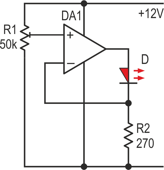
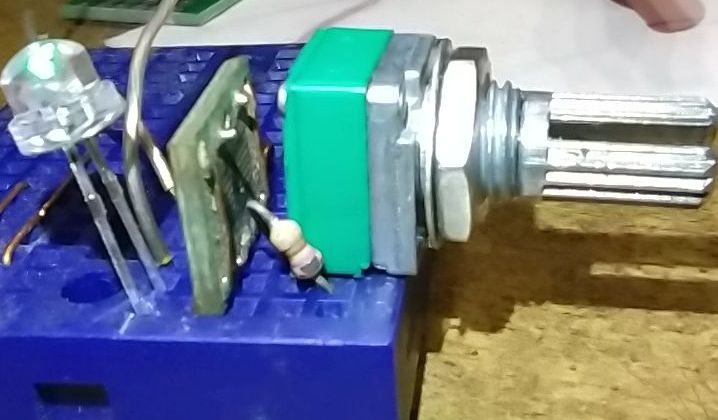
The simplest test of the op amp operation is a test in the current stabilizer circuit (Figure 1). Such a tester on a breadboard can be assembled in a couple of minutes, but as practice shows, you should forget about it. The op amp may seem to be working on DC, but on AC it is not.
|
||||
| Figure 1. | Current stabilizer for op amps testing; (a) – schematic diagram, (b) –photo of the layout. | |||
The circuit shown in Figure 2, the active component of which is the chip under test, together with any oscilloscope allows you to reliably determine the discrepancy of a general-purpose dual op amp with its specifications.
 |
||
| Figure 2. | Oscillator circuit for op amps testing. | |
Two op-amps are tested simultaneously: one in the oscillator circuit and other in the comparator circuit. Another op-amp (321MFX) in SMD package is placed on the vertical adapter and is used in the "active" ground.
So... An op amp with a Wien bridge in the positive feedback loop and an amplitude stabilization circuit in the negative feedback loop forms an oscillator. The greater the imbalance of the components in the bridge (static and dynamic), the greater the margin the feedback loop must have to maintain the set output level. It is for this purpose, unlike known circuits, that a matched resistive-LED optocoupler is used. The second op amp is connected to the oscillator output and is configured to operate as a comparator with hysteresis.
The chip is provided with a standard DIP8 socket. The SOIC8 version is enabled via an adapter. There are no special requirements for the bridge components. You can use regular dual potentiometers and capacitors with 10-15% tolerance.
Timing capacitors C1-C2 are installed in the header socket (Figure 3), allowing almost the full frequency range of the op amp to be tested if necessary. The capacitors pairs to cover the range of 14 Hz-140 kHz should have the following capacities: 1 µF, 100 nF, 10 nF, 1 nF. With high-frequency op amps, the circuit is stable up to 700 kHz, but the mismatch of the bridge values plays a bad role here.
 |
||
| Figure 3. | A photo of the generator prototype. | |
A homemade optocoupler (Figure 4) with a GL5506 photoresistor (peak spectral sensitivity is 540 nm) and a green SMD LED (510-555 nm) of 3014 footprint (3.0 mm × 1.4 mm) is used. Such a pair effectively performs its function at 100 µA LED current, does not load the op amp output and therefore does not add distortion. Yellow and white LEDs have been successfully tested. Don't forget to shade the optocoupler in bright light.
 |
||
| Figure 4. | Design of a homemade optocoupler. | |
The filter capacitor C3 can be omitted when working with frequencies above 1 kHz; the limited response time of the GL5506 (5 ms) ensures output stability.
The low frequency range (13-130 Hz) requires a capacitance of at least 120 μF. Otherwise, nonlinear distortions will increase sharply. A multilayer ceramic SMD capacitor of 1206 footprint with a capacitance of 47-100 µF can be recommended.
When testing low voltage circuits it may be necessary to adjust the amplitude with resistor R13 to avoid clipping. The oscillator is powered by an unstabilized 6-16 V source.
Power supply symmetry is ensured by the “active ground” circuit (Figure 5).
 |
||
| Figure 5. | An "active earth" circuit for symmetrical oscillator supply. |
|
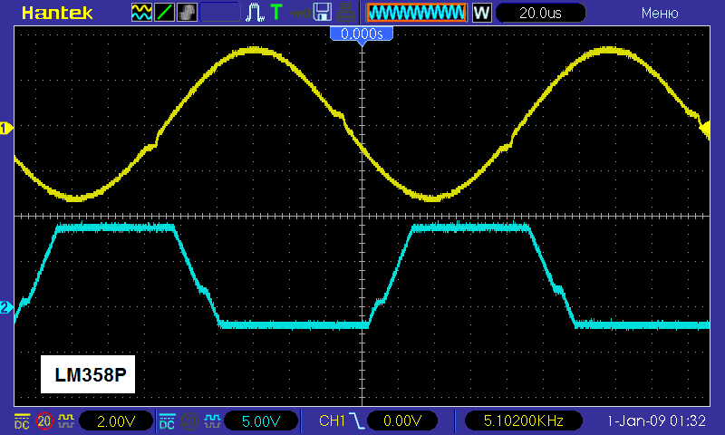
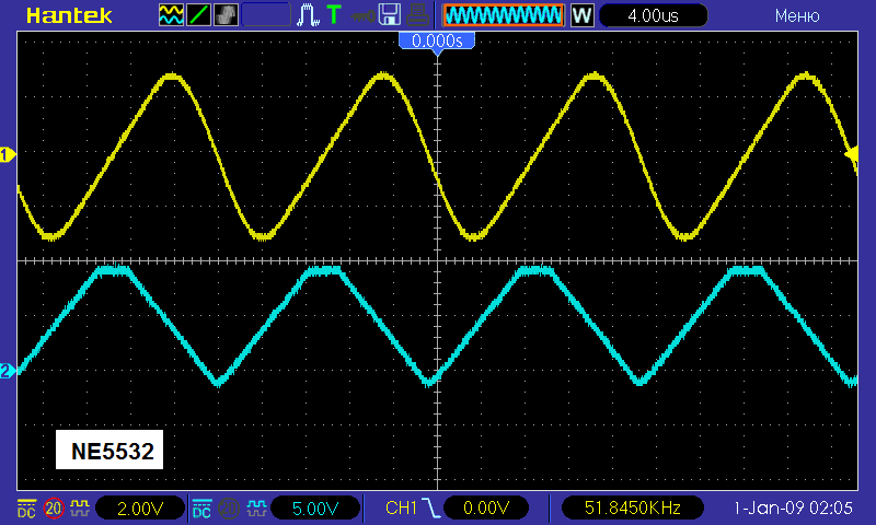
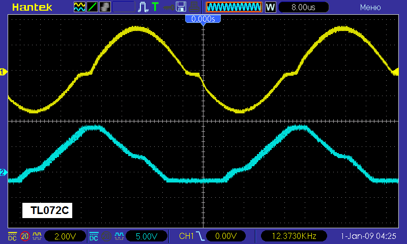
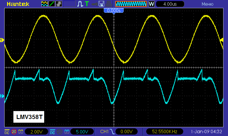
Figure 6 shows waveforms illustrating the results of testing several op amps with reputable markings, purchased on AliExpress recently from different sellers. Which chips would you use? The question is rhetorical. Only one sample refused to work in the proposed circuit. There was no crystal under the plastic.
|
||||||
| Figure 6. | Waveforms illustrating the results of testing several op amps. | |||||
Comments on the waveforms are best left to analogue circuitry experts, but it is clear that the output signal sine wave should be a sine wave. Crossover distortion are definitely a manufacturing defect. The comparator output, if it is asymmetrical relative to zero, may indicate the same thing. However, there are op amps that are not adapted to this mode, or the supply voltage is higher than the manufacturer's recommended voltage (LMV358T). The output screenshot allows you to calculate the rate of voltage change and, if it is less than the nameplate value – throw it in the bin. "Ideal" op amps are not represented in the waveforms.
