One option for driving high-brightness LEDs uses the standard stepdown buck converter (Figure 1). The sense resistor, RS, generates a feedback voltage, VFB, that sets the desired LED current, ILED, according to the equation

 |
|
| Figure 1. | A generic buck converter, IC1, provides constant-current drive for a high- brightness LED. |
Unfortunately, most buck converters require a relatively high feedback voltage on the order of 1 V, which dissipates high power in the sense resistor

 |
|
| Figure 2. | An op amp, IC2, increases the LED-current error signal and reduces power dissipation in the sense resistor. |
Reducing the sense resistor’s value and adding an op amp to boost the sensed voltage reduces the power penalty (Figure 2). In some cases, you can eliminate the op amp by using a stable reference voltage, which is available on some converter ICs, to pull up the sense voltage (Figure 3). The switching converter, a Maxim MAX1951, requires a feedback voltage of 800 mV and provides a 2 V reference voltage at the reference pin. Connecting R1, a 50-kΩ resistor, between RS and VFB, and R2, a 100-kΩ resistor, between the reference and the feedback pins shifts the operating point from 200 mV at RS to 800 mV at the feedback pin:

 |
|
| Figure 3. | Adjusting the feedback signal improves the efficiency in this buck-converter driver for high-brightness LEDs. |
Thus, for VSENSE = 0.2 V, V = 0.8 V. For the cost of two inexpensive resistors, power dissipation in the sense resistor diminishes by a factor of four.
 |
|
| Figure 4. | This graph shows LED current as a function of input voltage at half- load for the circuit of Figure 3. |
Using the Luxeon K2 LED from Lumileds, power measurements on the circuits of figure 1 and figure 3 illustrate how the feedback adjustment influences power that the LED driver delivers. Two graphs illustrate LED currents and voltages as a function of input voltage for a half-load of 400 mA (Figure 4) and a full load of 800 mA (Figure 5). As you would expect, the current regulation deteriorates at half-load. The variation of LED current averages approximately 5 mA over an input-voltage range of 4 to 5.5 V and 1 mA for the circuit with normal feedback. The input-voltage range, however, increases by more than 0.5 V. Regulation also deteriorates for full load, and the variation increases to approximately 22 mA versus 6 mA for the circuit with normal feedback (Figure 6). Again, the adjusted-feedback circuit of Figure 3 increases the input-voltage range.
 |
|
| Figure 5. | This graph shows LED current as a function of input voltage at full load for the circuit of Figure 3. |
You can define the improvement in efficiency, η, as follows:

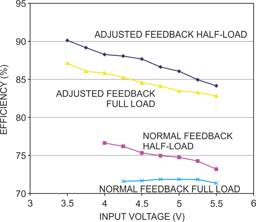
The buck converter’s power-conversion efficiency and power dissipated in the sense resistor determine the circuit’s efficiency. As Figure 5 shows, the adjusted feedback of Figure 3 increases the efficiency more than 10% at either half-load or full load. Assuming that the sense voltage doesn’t change, efficiency improves for lower output-current loads because the sense resistor dissipates less power.
 |
|
| Figure 6. | A comparison of a normal-feedback circuit (Figure 1) and an adjusted- feedback circuit (Figure 3) shows significant improvements in overall efficiency at half-loads and at full loads. |
