I'm not into cars to such an extent that I have an OBD-II analyzer in my toolkit. But when I discovered Chinese sources for $9-$20 USB & Bluetooth adapters, I couldn't say no.
Actually, my search for OBD capability was inspired by a persistent check-engine idiot light (spoiler: it was only a cylinder misfire – something I could have already told you before the light ever came on!). I found that the usual Chinese sources carried many wired & wireless adapters, and I ended up getting this one from the wonderfully named Banggood site. I knew it might not work, but it had good reviews, and I wasn't risking much.
Sure enough, it did work – well enough at least to report the misfire code and let me turn off the engine light. Then, curiosity got the better of me, and I had to see what was inside. I'll leave it to an enterprising reader to figure out the BOM cost. How can they make it so cheaply?
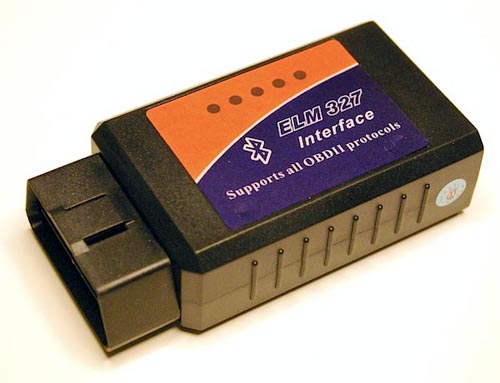
Here's the dongle – it doesn't know what's about to hit it. The LEDs do activate when the device is in use, but it's not clear if they have specific meanings. LEDless dongles of about 1/3 the size are also available.
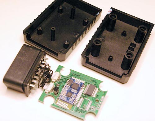
I thought it might have one of those easy-to-snap-together, hard-to-unsnap cases, but no, I found the screws.
A look at the guts – the overall quality is surprisingly high:
Looking at what I'll call the underside of the board reveals a Microchip MCP2551 CAN transceiver, a 4 MHz crystal, an Advanced Monolithic Systems AMS1117 3.3 V LDO in the upper-left (ever heard of them? I assume this is the same as an LT1117), five LEDs along the top, and a 78M05 5 V regulator at the lower-left. The two diodes to the right of the regulator made me think of varactors for some reason, but a code lookup shows they are probably 6.8 V Zeners.
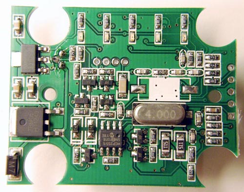
The quality of soldering and general manufacture is excellent. The only flux residue on this side of the board is from a 3-lead through-hole component, which brings us to the topside:
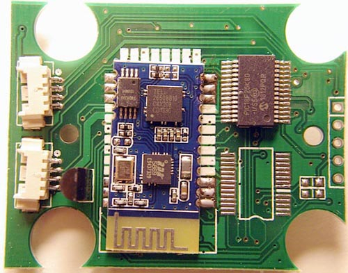
Now things get interesting, though let's start with the mundane. The through-hole TO-92 is a good old LM317 regulator. The two connectors did not "flow" into alignment very well, even though they have their "ears" soldered to the board. I'll guess that the unpopulated chip is for a serial-to-USB converter for a wired version of the board. The big chip is a PIC18F25K80 — not too shabby a part, with 32 K flash, 3.5 K RAM, 1 K data EEPROM, CAN, 12-bit ADC, 16 MIPS, etc. It alone is worth about $2 in decent quantity!
That leaves the very badly soldered Bluetooth module, blue soldermask and all. The top three contacts on the left edge aren't even soldered! Are they supposed to be? I could compare it to the original unit I bought (I haven't actually tried this one).
The chips on the Bluetooth module comprise an FM24C64, which I assumed was just a common 64 Kb EEPROM, but actually appears to be a more exotic FRAM! That's the first FRAM I've seen in the wild. The chip to the right of the FRAM has me stumped. Let us know if you can figure it out. But the IC at the lower-right is an RDA Microelectronics RDA5869 Bluetooth SoC, a 55 nm design with an ARM7 µC.
Many of the components have this year's date code, so production is current. I get the impression the firmware in these cheap units might actually be…ahem…borrowed from an original design, and I don't know how well it works with the range of car models and years sporting OBD-II, but it did what I needed for my 1998 Toyota.