Jose Blanes
EDN
Rectifier circuits based on semiconductor diodes typically handle voltage levels that greatly exceed the diodes' forward-voltage drops, which generally don't affect the accuracy of the rectification process. However, the rectified signal's accuracy suffers when the diode's voltage drop exceeds the applied voltage. Precision rectifier circuits combine diodes and operational amplifiers to eliminate the effects of diode voltage drops and enable high-accuracy, small-signal rectification.
By taking advantage of modern operational amplifiers that can handle rail-to-rail inputs and outputs, the circuit in Figure 1 dispenses with diodes altogether, provides full-wave rectification, and operates from a single power supply.
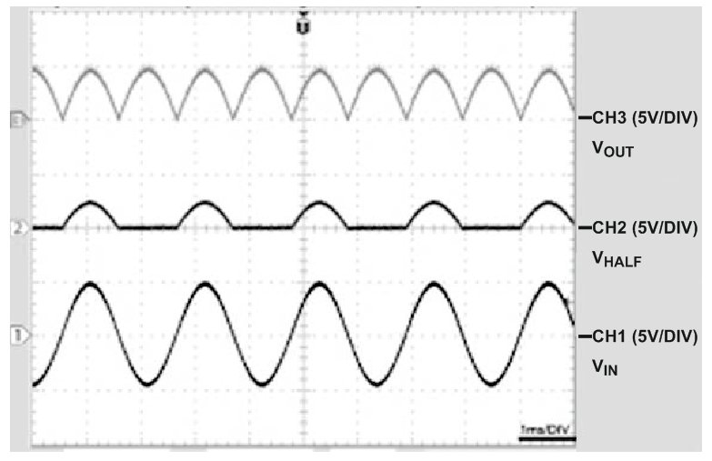
The circuit operates as follows: If VIN > 0 V, then IC1A's output, VHALF, equals VIN/2, and IC1B operates as a subtracter, delivering an output voltage, VOUT, equals VIN. In effect, the circuit operates as a unity-gain follower. If VIN, 0 V, then VHALF = 0 V, and the circuit behaves as a unity-gain inverter and delivers an output of VOUT = –VIN. Figure 2 shows the circuit's input signal at VIN; its intermediate voltage, VHALF; and its output voltage, VOUT.
 |
|
| Figure 2. | From bottom to top, the waveforms show VIN (CH1), VHALF (CH2), and VOUT (CH3). |
The circuit uses a single National Semiconductor LMC6482 chip and operates in the linear regions of both operational amplifiers. Suggested applications include low-cost rectification for automatic gain control, signal demodulation, and process instrumentation. The circuit relies on only one device-dependent property: The amplifiers must not introduce phase inversion when the input voltage exceeds the negative power supply; the LMC6482 meets this requirement.

