Anthony H. Smith
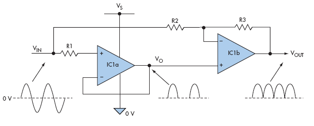
A full-wave rectifier can be built without using any diodes. It exploits the fact that the output voltage of certain single- supply op amps is effectively “clamped” to ground (0 V) when the input signal goes negative. The circuit combines a unity-gain follower (IC1a) and a second stage (IC1b) that combines the follower’s output signal (VO) with an inverted version of the input signal (VIN) (Fig. 1). The circuit’s output voltage (VOUT) is defined by the following expression:
VOUT = (1 + K)VO – KVIN (V)
where K = R3/R2. During the positive-going portion of the input signal, the follower tracks the input voltage so that VO = VIN. Therefore, VOUT = (1 + K)VIN – KVIN = VIN.
 |
|
| Figure 1. | This full-wave rectifier needs just two op amps and a few resistors—and no diodes. |
During the negative-going portion of the input signal, the follower’s output is “clamped” to ground whereby VO = 0. Therefore, VOUT = – KVIN. By making R2 = R3 so that K = 1, VOUT = – VIN, and the circuit inverts the input during negativegoing portions. Consequently, provided that the input signal swings symmetrically about ground, the overall transfer function is: VOUT = |VIN|.
It’s important that the op amp you select be able to handle negative-going signals safely and without phase reversal, and the input and output common-mode voltage range must include ground. During negative signal excursions, resistor R1 limits the input current to a safe value, typically less than 10 mA. Without R1, IC1a’s noninverting input could be damaged by large negative-going voltages.
The op amp must also be fast enough to recover rapidly from the “ground clamped” condition at the point where the input signal starts to go positive. Otherwise the output signal could suffer distortion, which is particularly noticeable at high frequencies. Provided the op amp is a rail-to-rail variety, the signal swing is limited only by the magnitude of the positive supply rail (VS).
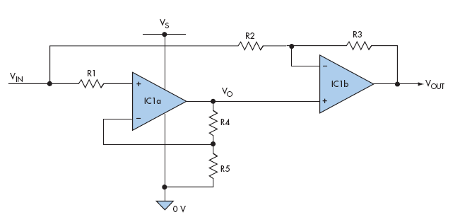
You can introduce gain to the circuit simply by adding two resistors, R4 and R5 (Fig. 2). The ratio of R4 to R5 is found from the following relationship where K (= R3/R2) is the overall gain required:
(R4/R5) = (K – 1)/(K + 1).
 |
|
| Figure 2. | Gain can be added to the circuit in Figure 1 by adding R4 and R5. |
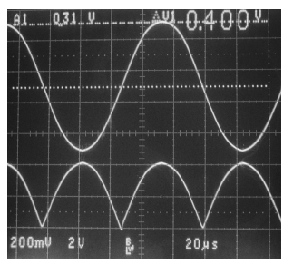
For example, if you require a gain of 10, then R3 = 10 × R2, and R4/R5 = 9/11 = 0.818. The oscillogram shows the circuit’s response to a 10-kHz sinewave with the following components chosen to provide a gain of 10: R2 = 3.3k, R3 = 33k, R4 = 8.2k, and R5 = 10k (Fig. 3). Input resistor R1 was 10k, the supply voltage (VS) was 5 V, and a Texas Instruments OPA2374 dual op amp was used for IC1. The input sinewave has a peak amplitude of 400 mV, and the output signal swings from 0 to 4 V.
 |
|
| Figure 3. | The oscillogram for the circuit shows 10-kHz sinewave response (Gain = 10) (20 µs/division). The top trace is the input signal (200 mV/ division) and the bottom trace is the output signal (2 V/division). |
Remember that the input signal must swing symmetrically about ground. Thus, ac coupling may be required if the source voltage has a dc offset.