Question:
I’m selecting an op amp for my precision signal path. Isn’t faster always better?
Answer:
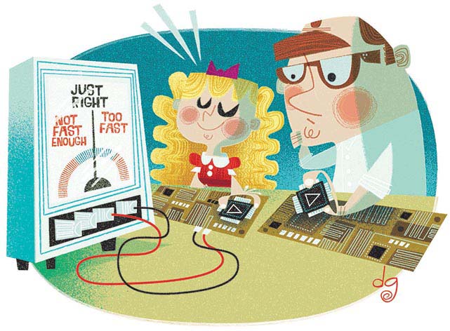
Choosing the appropriate bandwidth for an application of a precision op amp is a lot like the experience of Goldilocks trying to choose between the three bears’ bowls of porridge – one bowl was too hot, one bowl was too cold, and one was just right. We would like an amplifier that is not too slow and not too fast but gives our signal all the gain and speed necessary to maintain stability and accuracy.
The key op amp specifications for a voltage feedback op amp in this application are the gain bandwidth product (GBP) and the phase margin (PM). Figure 1 shows the open-loop gain and phase vs. frequency for the ADA4610, a popular precision op amp. The plot shows that the op amp gain at low frequency is greater than 30,000 (90 dB), rolling off at 20 dB per decade, and reaching unity (0 dB) at about 10 MHz – known as the unity-gain crossover frequency. The op amp open-loop gain plot gives us the ability to determine its GBP and design an amplifier circuit with a given closed-loop gain and bandwidth such that GBP = gain × BW, as shown in Figure 2. For example, notice how a one decade decrease in closed-loop gain (AV) from 100 (or 40 dB) to 10 (or 20 dB) results in a one-decade increase in bandwidth, from 163 kHz to 1.63 MHz.
 |
||
| Figure 1. | Open-loop gain and phase vs. frequency. | |
Similarly, the op amp phase plot in Figure 1 relates to the inherent phase shift of a signal as it passes through the op amp. The phase margin can be approximated by reading the phase shift at the bandwidth of the amplifier circuit. In the case of the ADA4610, it is approximately 67°, which is plenty of phase margin for stability. If the system design causes the phase margin of the amplifier circuit to decrease to the point that it is too small, it can manifest with symptoms like significant ringing at the output or even oscillation.
In addition to stability, accuracy is affected by frequency. At low frequencies, the open-loop op amp gain (AVOL) is highest and is sometimes referred to as the dc gain. As the frequency increases, the gain decreases and gain error gets worse. Thus it doesn’t take much frequency until we start seeing gain error that may be too great for a precision sensor signal.
 |
||
| Figure 2. | Closed-loop gain vs. frequency. | |
The amount of closed-loop gain can be calculated using the following equation. Where β is the feedback factor, 1/β is the ideal closed-loop gain (say, 100 V/V in the green line in Figure 2), and the product Aβ is called the loop gain.

As the loop gain decreases with frequency, we see an increase in gain error. The percentage of error can be calculated by the following equation:

Graphically, think of the loop gain Aβ as the difference between the open-loop dc gain in Figure 1 (and also listed in the data sheet specifications) and the closed loop gain in Figure 2. For example, using a nice round number of 100 dB for the op amp open loop gain, and an ideal closed-loop gain of 40 dB, we get a loop gain of 60 dB (or 1000 V/V). Table 1 demonstrates that increasing loop gain gives us less error (more precision).
| Table 1. | Increasing Loop Gain Decreases Error | |||||||||||||||
|
||||||||||||||||
So, if more bandwidth and loop gain is better, why not use an op amp with a GBP much, much higher than that of our signal gain and bandwidth? There are a number of reasons not to use excessive GBP. The broadband noise of an op amp integrates over the bandwidth of an amplifier. If we choose an op amp bandwidth greater than necessary, there will be excessive noise that will be gained up by the amplifier circuit and reduce the system’s signal-to-noise ratio. Higher speed op amps are more susceptible to system parasitic capacitance, which can add lag to the feedback signal and reduce the phase margin and therefore the stability. Finally, faster op amps consume more power because the idling current on the op amp output stage must be higher in order to drive load capacitances at a higher frequency.
Choosing the fastest op amp can burn you on power and signal quality. Picking too slow of an op amp can leave your accuracy, stability, and other performance measurements in the cold. Finding the op amp with the right balance of speed, gain, accuracy, and phase margin for your application will be just right.
References
- Castro, Gustavo. Citius, Altius, Fortius. Analog Dialogue, Rarely Asked Questions – Issue 128. Analog Devices, Inc.
- Jung, Walter G. Op Amp Applications Handbook. Analog Devices, Inc., 2002.
- Tutorial MT-033. Voltage Feedback Op Amp Gain and Bandwidth. Analog Devices, Inc., 2009.
- Tutorial MT-44. Op Amp Open-Loop Gain and Open-Loop Gain Nonlinearity. Analog Devices, Inc., 2009.