James Patterson, National Semiconductor
EDN
There are more than 2 million installed TRIAC dimmers worldwide, and they can prove a challenge to the control circuitry of an LED light. With such a large base, backward compatibility is a must.
The lighting industry has relied on the incandescent bulb for more than a century, and, over the last 50 years, the phase dimmer has become the main dimming control. Standard forward-phase, or TRIAC (triode-alternating-current), dimmers are notoriously difficult to interface with LED drivers. To make things worse, the performance of each dimmer varies greatly. Although there are newer, better reverse-phase dimmers available, the standard forward-phase dimmer is so common in the world’s electrical infrastructure that LED-lighting manufacturers simply cannot ignore it. As usual, backward compatibility is paramount.
Forward-phase dimmers
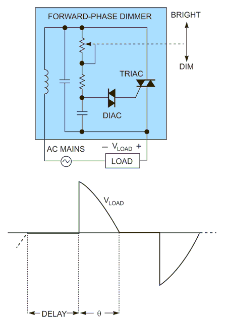
A standard forward-phase dimmer contains a TRIAC, a DIAC (diode-alternating-current), and an RC (resistance/capacitance) circuit (Figure 1). A potentiometer controls the resistance, and the resulting RC time constant controls the amount of delay before the TRIAC turns on, or the firing angle. The portion of time when the TRIAC is on is the conduction angle, θ. The resulting voltage waveform is a phase-cut sinusoid.
 |
|
| Figure 1. | A standard forward-phase dimmer contains a TRIAC, a DIAC, and an RC circuit. |
This type of dimming works well in incandescent bulbs, which are simple resistive loads. The time-averaged voltage across the filament’s resistance decreases as the conduction angle decreases, providing naturally smooth dimming.
The TRIAC also has a minimum holding-current requirement. The current flowing through the TRIAC must remain above this minimum level to ensure that it remains on throughout the entire conduction angle. The incandescent load easily satisfies this condition because of the load’s inherent power levels—40, 60, and 75 W, for example.
Compatibility with LEDs
Unfortunately, solid-state lighting lacks the benefits of the phase-dimming approach. An LED is a semiconductor device; controlling light output is accomplished by regulating its forward current. High-brightness LEDs, which can conduct hundreds of milliamps to amps of current, almost always use a switching converter to maintain system efficiency.
A standard switching converter regulates its output regardless of the average input voltage, meaning that the phase-chopped waveform that the phase dimmer provides must first be decoded. The decoded information can be used to control the reference for output regulation. Although this task is relatively simple for power-electronics designers, many complexities hide under the surface.
An obvious difference is that the load is no longer purely resistive. Instead, the converter looks like a reactive load to the phase dimmer due to both capacitive and inductive components within the circuit. This condition causes a standard converter to have problems with the fast rising edge of the phasechopped voltage. Designers usually will employ standard RC-damping methods to reduce the problematic ringing that this rising edge induces. However, this approach always involves extra power loss.
An even larger problem comes from an unexpected source. The efficacy of modern LEDs is far superior to that of incandescent bulbs, which waste more than 75% of their light output in the infrared spectrum as heat. LEDs, on the other hand, provide most of their light output in the visible spectrum. The newest high-brightness LEDs are five to six times more efficient than comparable incandescent lights, meaning that a current LED replacement for a 60 W bulb or fixture could be as low as 10 to 12 W. This power savings is great for the consumer but not for the phase dimmer, which has the minimum holding-current requirement.
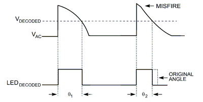
When dimming an LED fixture, the TRIAC may misfire—that is, conduct insufficient current to remain on for the whole conduction angle. Because the misfires are usually asymmetrical in consecutive rectified ac-line cycles, the decoded angle can oscillate between two or more points. This oscillation manifests itself as visible flutter and flicker of the light output because of the low frequency. To prevent visible flicker, the converter must burn extra power to ensure that the TRIAC does not misfire.
Sacrificing efficiency
Burning extra power is contrary to the main goal of power-converter design: to provide efficient, well-designed, high-quality power processing. So the task for designers becomes two-fold: to provide efficient power conversion from the ac mains to the LED load and to ensure that the phase dimmer functions properly while minimizing excess power loss.
 |
|
| Figure 2. | Most LED systems employ some form of PFC, which forces the voltage and current to stay mostly in phase. As a result, the phase dimmer usually misfires toward the end of the conduction angle where the voltage and current are decreasing and creates a varying angle decode, depending on where the misfire occurs. |
New regulations for power quality now require PFC (power-factor control) for many LED systems. PF (power factor) is a measure of how well energy transfers from the input to the output of a converter. If the input current is free of distortion and perfectly in phase with the input voltage, the PF is one. Any phase shift or distortion of the input current due to reactive elements and switching noise decreases the PF.
Because most LED systems employ some form of PFC, the input current usually fairly well follows the input voltage, meaning that the phase dimmer usually misfires toward the end of the conduction angle where the voltage and current are decreasing (Figure 2). This misfire creates a varying angle decode, depending on where the misfire occurs.
Initial approaches
A simple approach to meeting the holding-current requirement is to add a load resistance that ensures the design will meet the minimum input current condition across the full conduction interval. This method is highly inefficient. For a 100 W incandescent downlight replacement where only 15 W of LEDs is necessary, this fixed hold current can cause a 10 to 20% efficiency drop.
A more complex approach is to linearly add the load every cycle, which involves ramping up the extra hold current during the conduction angle until it reaches the maximum at the end. This method can greatly reduce the efficiency drain; it is, however, difficult to design over a large operating range.
 |
|
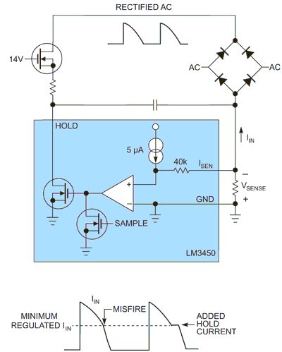
| Figure 3. | A dynamic-hold circuit draws no extra hold current when the input current is higher than the regulation point. Below the regulation point, it draws enough current to maintain the minimum-hold requirement. |
For example, in an 85 to 305 V-ac universal input 15 W LED downlight, the worst-case hold-current condition occurs at 305 V ac, when the input current is at a minimum. To ensure that the TRIAC remains on over the entire conduction angle at 305 V ac, you must add a fairly large amount of hold current. Because it is a universal design, the hold current you add at 85 V ac would be approximately four times larger than necessary—a large waste of power.
Dynamic hold
The best way to maximize efficiency is to regulate the minimum input current. This approach draws no extra hold current when the input current is above the regulation point. Below the regulation point, the circuit draws enough current to maintain the minimum hold requirement. The LM3450 controller implements this method, called dynamic hold (Figure 3). A sense resistor between the diode-bridge return and system ground provides a method for input-current sensing. Using the sensed voltage across that resistor, the controller linearly draws current through the hold pin to maintain the minimum regulated input current. This ensures that any extra power dissipation is minimized.
Ultimately, the dynamic hold is necessary to ensure that the phase angle is being properly decoded to provide an accurate dimming command to the converter. The idea is to keep the TRIAC from misfiring during decoding so that the angle does not sporadically change, causing flickering. Looking closer at the system, it is actually unnecessary to decode the angle every cycle. A sampled system could provide even more efficiency relief. In this approach, the extra holding current would need to be added only during the sampling interval when decoding is taking place. During the non-sampled cycles, no current would be needed.
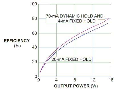
The LM3450 employs this sampled-phase-decoder scheme, and the dynamic hold is thus active only during the sampling interval. To validate this approach, a 120 V, 15 W downlight application is implemented with both a fixed 20-mA holding current and a much larger 70-mA dynamic holding current (Figure 4). The 70-mA dynamic hold ensures a complete dimming range with more than 20 tested dimmers and yields an efficiency improvement of as much as 6%.
 |
|
| Figure 4. | The results for a 120 V, 15 W downlight application using both a fixed 20-mA input load and a 70-mA dynamic hold show that the 70-mA hold ensures complete dimming range with more than 20 dimmers and yields an efficiency improvement of as much as 6%. |
The designer has one difficult challenge using this approach. The previous analysis omits the impact of the EMI (electromagnetic-interference) input filter on the converter. Every converter requires filtering to pass standards regulating conducted and radiated EMI. Unfortunately, adding reactive components on the ac side of the rectifier bridge distorts the input-current measurement on the dc side. This problem becomes worse at the end of the conduction angle, when the dV/dt (rate of voltage change) of the input voltage is largest. At this point, the converter draws much of its current from the EMI capacitors, and the TRIAC conducts even less current than expected.
To deal with the sensing inaccuracy, the regulated minimum input current should be increased and the EMI filter capacitance minimized.
