If you have high-powered LEDS, or a power supply, or are trying to control larger motors, you have to get a lot of heat out of your circuit boards. The classic way to dissipate heat is to bolt your power transistor to an aluminum heat sink. That is a slow, messy, and expensive proposition, especially if you need thermal grease between the transistor and heat sink (Figure 1).
 |
||
| Figure 1. | This 5V regulator can supply more power when bolted to an aluminum heatsink using thermal grease to better transfer the heat. |
|
Another problem with bolted-up heatsinks is that the assembly operation is less controlled. Circuit board fabrication and assembly are tightly-controlled repeatable processes. When you have people hand-assembling things there is a greater chance for errors. This is especially true if the people doing the work are on the other side of the world, speak a different language, and are functionally illiterate.
It’s always a good idea to make thermal management inherent in your PCB design. Experience has shown you can get about 2 W of heat out of a 3×5” copper area on a conventional FR4 PCB.
Wayne Yamaguchi learned some great thermal design tips for his kits to convert a Maglite to an LED flashlight (Figure 2). He thought the hard part would be the switching regulator design. It turns out the mechanical engineering and thermal design was the hardest thing.
 |
||
| Figure 2. | Wayne Yamaguchi found that Linear Tech had made the circuit design for his LED Maglite kit easy, it was the thermal design that took the most work. |
|
Wayne figured out how to use vias and copper pours to get the heat of the LED transferred to the aluminum body of the Maglite. Getting the heat out is why LED flashlights are not made of plastic. An LED is more efficient than an incandescent bulb, but the incandescent bulb radiates its waste heat out as IR (infrared) light, along with the viable light. The heat made by an LED stays in the LED.
The first place you look to dissipate more heat is in the PCB copper. You may want to experiment with thicker copper. Normal PCBs have 1 oz copper, or 1 oz plated up to 2 oz copper. That is measured in ounces per square foot. To convert to the actual thickness in mils (thousandths of an inch), you multiply by 1.37. It’s easy to order PCBs with 6 oz/ft2 copper foil. Then you go to what PCB fabricators call “heavy copper,” where the weight can get up to 20 oz/ft2, that is, 27.4 mils thick. If you need even thicker, you can shop around for a PCB fab house that does “extreme copper.” This is anything above 20 oz/ft2 thickness.
Any airflow over a heatsink or copper planes will greatly improve heat flow. If you uncover the solder mask of the plane, it improves heat transfer to ambient. Do not finish these large bare copper areas with HAL (hot-air-leveling). The solder can pile up and while it will improve heat dissipation, it will make big droopy lumps of solder. It is better to nickel plate or use gold immersion finishes. Both will protect the copper from corrosion and the gold finish looks great.
When the PCB cannot get enough power out, you can increase the number of output transistors, if you have the board area to spend. Linear Tech helps you do this with their linear regulators that you can parallel together (Figure 3). If you have a 5 W dissipation, you can use three devices in parallel. Each device is good for 2 W if you give it enough PCB copper area to dissipate that heat. You can use interior planes to move the heat, but remember, you have to use vias to stitch to the inside planes, since ultimately, you have to get the heat to the outside air.
 |
||
| Figure 3. | Linear Tech helps you get the heat out of their surface-mount parts so you don’t need an aluminum heat sink. |
|
If paralleling surface-mount devices (SMD) and thicker PCB copper is not enough, you might look at transistors like International Rectifiers “Direct FET” line, also know as Infineon’s CanPAK (Figure 4). They have a package that lets you mount a heatsink on the top. Now you can use all the thick and heavy copper tricks on three terminals. You can also bond, press, or solder a heat sink on the top of the part, which is the die lead-frame.
 |
||
| Figure 4. | The CanPAK package from Infineon transfers the heat from the back to the chip die to the PCB using a broad metal frame. |
|
For switching regulators with internal FETs, or conventional packaged FETs, you can also use a gull wing or top-hat heatsink that transfers the heat from the PCB to the air (Figure 5). The great thing about this solution is that you can use pick-and-place assembly for the heatsinks like the other parts on your board. Then you send the board into your normal IR reflow oven to solder both the part and the heatsink. Do make sure that your CAD “insert” file places the heatsink after the FET is placed. You should make a note on the assembly drawing as well.
 |
||
| Figure 5. | Top hat heat-sinks take the heat out of your PCB and allow pick-and-place assembly (courtesy Fischer Elektronik). |
|
Putting a heat sink on the plastic part will have little value. The heat travels through the plastic package so slowly that a metal heat sink on the plastic does very little to cool the silicon die itself. The best place to remove heat is through the lead-frame that the die is mounted to. In most parts, that lead frame is also the ground or common, or the V− pin. Some CMOS parts have the lead-frame connected to V+. Check with the IC company before you make assumptions on how to remove the heat.
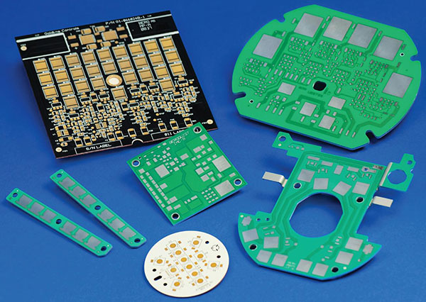
When you really need to move a lot of heat, perhaps in a hot environment like under the hood of a car, you can go to metal-core PCBs (Figure 6). The nice thing about metal core PCBs is that they move a tremendous amount of heat, and they are also strong structural components. The bad side is that metal-core PCBs tend to be expensive in low volume. PCBPool can do prototyping services for metal-core PCBs.
 |
||
| Figure 6. | Metal-core PCBs are often the only way to get enough heat out of LED circuits (courtesy Bergquist/Henkel). |
|
There is a newer proprietary heat and high-current PCB technology (Figure 7). The company Häusermann calls the process HSMtec. They bend and bond 20 mil wires to the board. These wires and strips piggyback on existing traces you design on the PCB. So now any narrow trace can carry much more current and heat. The 2 mil thin strips can be quite wide, so you get the same benefit as extreme copper or metal-core PCBs.
|
||||||
| Figure 7. | Häusermann has a propriety process that makes PCBs that can conduct a great amount of heat or current. |
|||||
An example
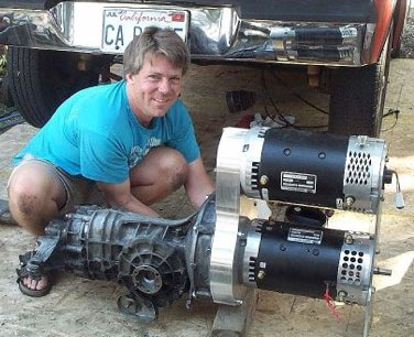
When it comes to good thermal design there is no better example than Otmar Ebenhoech and the Zilla line of dc electric car motor controllers (Figure 8). If you watch the PBS show about White Zombie, one of the quickest electric drag racers on Earth, you can see the Zilla controllers when the show looks under the hood.
 |
||
| Figure 8. | Otmar Ebenhoech kneels next to his dual dc-motor conversion for his 914 Porsche. |
|
Otmar explained the thermal design tradeoff years ago. He started with a big IGBT module. They were hard to drive and hard to get the heat out of. Otmar has many blown-up modules on the wall as souvenirs. His epiphany was that it’s easier to remove the heat from multiple IGBT transistors. So he uses 36 IGBTs in TO-247 packages. When I asked why he didn’t use MOSFETs, Ebenhoech noted, “At max current for the part, IGBT’s have much lower power loss in the 600 V range. The standard Zilla Z2K runs 2000 A motor current.” With the heat sources spread out, Otmar uses water-cooled copper heatsinks to get the heat out. The storage capacitors are essential to lower the impedance of the power fed to the FETs. At these current levels, even the tiniest inductance in the bus will mean big switching spikes that blow up IGBTs and waste power.
Otmar recalls that the most fun part of the design was the puzzle aspect of the mechanical engineering. “You have to keep the capacitors as close to the IGBT as you can, but you also have to get the heat out of the IGBTs.” Then there is the 0000 cabling to handle the current, plus you need to engineer a very good “ground” system so that the other side of the capacitors see a low impedance. Each IGBT has a clamp diode as well, that has to be kept close to minimize the size of the current loops.
The other brilliant thing Otmar did was to design in an 8-bit PIC Microchip microcontroller to monitor and control all the aspects of the power conversion. These days maybe you could use a ARM Cortex M0+ microcontroller, a 32-bit chip. That way you can have a TCP/IP stack, if you want to connect your controller to the Internet with Wi-Fi. Ebenhoech remarks, “The PICs were selected in 1999, these days I’d use something much faster. Have you seen the Teensy 3.6? It’s my favorite development board now; it’s got two CAN buses.”
So whether you are designing an LED lamp or an electric drag racer, know your options and the need to get the heat out of the electronics. If you make sure to design for worst-case conditions and actually test at these conditions, you can assure a long and happy life for your designs.


