James Lockridge, Texas Instruments
Electronic Design
Rather than use a fixed-rail voltage source, it’s more efficient and flexible to utilize a current source so that performance remains consistent while supply rail and coil resistance change.
Relays and solenoids are available with many different voltage ratings. Most factory- and process-automation equipment operates from 24-V supplies. However, customers may have control signals for a wide range of ac or dc voltages, such as 12 V, 24 V, 36 V, 48 V, or even 120 V or 220/240 V for some valves and contactors. For each voltage, the coil designs of the variants must be different. Having coils to accommodate all of the possible voltage adds to inventory, BOM, and spare-part headaches.
One solution could be to design one coil for 12 V, then use a resistor to limit the current into the coil for each voltage option. However, this wastes energy and dissipates heat from the resistor, especially if the 12-V coil is used for the 220/240-V design.
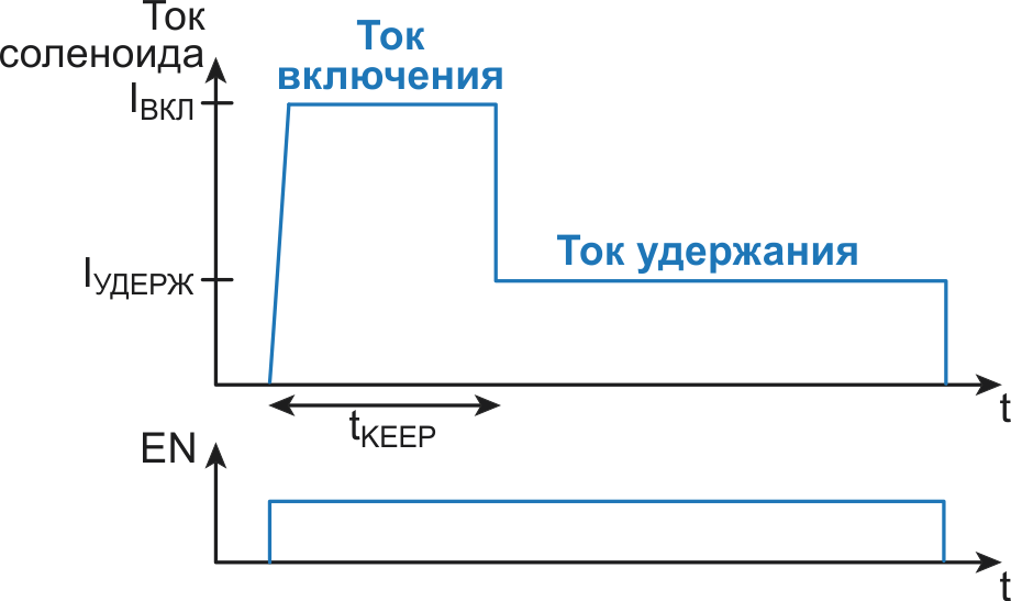
A more energy-efficient solution is to use pulse-width modulation (PWM) driving and a freewheeling diode to regulate the current in the solenoid. In addition, you could add current-sense feedback with PWM and control the current in the solenoid. Using a PWM driving method can also allow you to shape the current-drive profile to have a higher pull-in current for actuation, then drop to a lower current to hold the solenoid in place and save power in the long term (Fig. 1).
 |
||
| Figure 1. | Here’s an example of how current shaping with PWM can save power in the long term. |
|
While PWM driving without current-sense feedback is easy to implement, variations in coil resistance, temperature, supply voltage, and the other factors can cause unintended solenoid de-actuation. As temperature increases, the resistance of the coil will increase. According to Ohm’s law, the increased resistance will cause the current to decrease. Since current is responsible for generating the magnetic force, when the current decreases, so will the magnetic force.
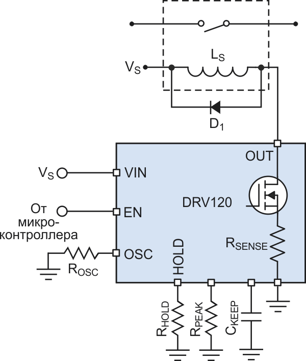
Thus, using PWM driving with current-sense feedback is a more reliable driving method for the coils and relays. With current control, the driver regulates the coil current to the required value independent of resistance, which makes the system more robust over temperature. You could implement current-sense feedback with a microcontroller and discrete signal-chain components, or use an integrated solenoid/relay driver such as the DRV120 (Fig. 2).
 |
||
| Figure 2. | Using current control rather than voltage for relay/solenoid driving, here utilizing the DRV120, maintains the desired drive level independent of rail voltage or change in coil resistance with temperature. |
|
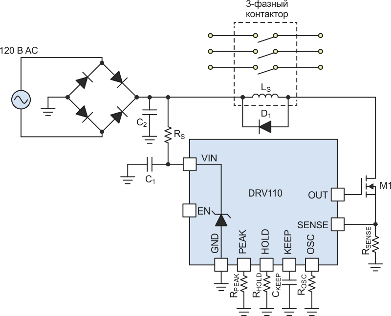
To accommodate ac-line power applications with PWM driving, the ac voltage must first be rectified. A driver such as the DRV110 (similar to the DRV120) can then handle the large dc voltage with a current-limiting resistor and a Zener diode. The rectified ac power then drives the solenoid or valve control directly (Fig. 3). Using dc to drive a contactor instead of ac simplifies the design of the magnetics by eliminating the need for a shaded ring in the coil core.
 |
||
| Figure 3. | The DRV110 can operate from a 120- and 230-V ac supply (as well as low-voltage dc) through the rectifier and resistor to drive the coil for an ac contactor. |
|
With this current-control technique, you can design only one 12-V coil with your desired force requirements for any ac or dc supply of 12 to 48 V and potentially even up to 120 to 220 V. This allows you to have multiple product offerings while only needing to design for one coil.
Another challenge exists when the designer wants to use a particular relay or solenoid, but the available supply-rail voltage is too high; for example, when the coil is rated for 12 V but the supply rail is 24 V. While one “obvious” solution is to just switch to a unit with a 24-V coil, doing so may not be easy in reality: Perhaps it also involves adding the new part number as an approved component, which may be a difficult and lengthy process, or there’s a need to get the final product to market quickly. Or, perhaps the design needs the force specifications of a particular solenoid; however, it’s rated for 12 V but you only have a 24-V rail.
Using current control can solve this dilemma, since designers can utilize the 12-V relay or solenoid for both 12- and 24-V systems, and even be prepared for a next-generation product that may have a 36- or 48-V supply rail. Thus, current control will allow continued use of the chosen solenoid or relay, and maybe by using the same solenoid in all three systems, those who procure the parts on the BOM can get a volume discount for purchasing large volumes of that particular part number.
