Paul Rako
Electronic Design
A look inside the drive brought interesting revelations in terms of the overall design, and unearthed a rather perplexing part
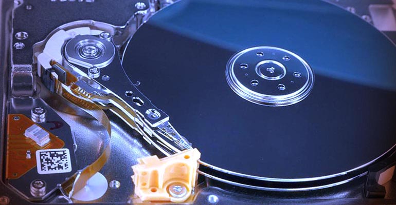
I have two Samsung 1.8-in. USB disk drives that I use to back up all my work. They have a capacity of 250 GB. I kept one in the safe-deposit box and rotated it with the other one about once a month. Now I use 1-TB solid-state drives to back up my work off-site. I dug the Samsung drives out of the drawer to see if they still worked. One of them did, but only once. After copying a bunch of music files to the disk, it functioned for a few days, and then would just hang my Windows 7 laptop. For an engineer, it was a perfect opportunity to take something apart (Fig. 1).
 |
||
| Figure 1. | The Samsung 1.8-in. disk drive uses two platters to achieve a capacity of 250 GB. |
|
What I liked about the drive was its diminutive size (Fig. 2). Its smaller than a deck of cards, but would hold all my work. Being USB, I could take a drive into work in case I needed some old file from previous jobs. One reason I dug it out of the drawer was to see if it could serve music to my new Joying Android car stereo. Turns out the Joying saw it and played the music, but since I formatted this drive NTFS years ago, I may have bricked it when plugging it into the radio. Forums say that most car stereos want FAT32 file systems for external storage.
 |
||
| Figure 2. | Samsung’s 1.8-in. disk drive has a USB controller built in and is powered solely by the USB connector. |
|
The drive was mounted in the plastic enclosure with two slip-on rubber shock absorbers (Fig. 3). Consumer product manufactures seem to love Kapton tape, as evidenced by the small piece stuck to the USB connector housing.
 |
||
| Figure 3. | Rubber bumpers cushion the disk drive inside its plastic case. | |
Elegant Guts
The guts of the disk drive are elegant and well-designed (Fig. 4). From left, the top housing is injection-molded, with a black damping pad in the center. The pad and some screws are tossed inside for the picture. The label is above it. Next is one of the rubber shock mounts. The top sheet-metal case of the drive is next, with the spindle nut and one of the platters above it. Next is the magnets and head assembly. Above them is the spacer between the two platters. Next is the bottom sheet-metal case, with the spindle motor still in place. To its right is an orange plastic parking component for the head, along with the other rubber shock mount. To the right of that is the PCB (printed circuit board) that mounts all of the electronics. It has a large hole and a corner missing, making the drive as thin as possible. Above the PCB is a metallized foil patch that connected to the shell of the USB connector and covered the USB bridge chip. At the far right is the bottom cover, with an insulating spacer that went in between the PCB and the drive. The black damping pad is underneath the spacer in its correct location.
 |
||
| Figure 4. | Spread out, the pieces of the disk drive reveal precision manufacturing in a high-volume consumer product. | |
The PCB has vias stitched along its edges to prevent electromagnetic interference (EMI) from radiating out the edge of the board (Fig. 5). This is the side of the board that faces out. At the left is the connector that connects to the flying read head. The crystal and JM20335 USB-to-ATA bridge chip were covered by that metallized pad.
 |
||
| Figure 5. | The PCB in the disk drive is shaped to fit. | |
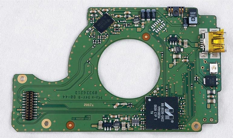
The inside-facing side of the PCB holds a Texas Instruments TLS2309 controller chip (Fig. 6). This chip runs the spindle motor. Also on the top edge is the connector for the spindle motor. A large tantalum capacitor sits next to it, to supply surge current. At the bottom is the Marvell 88i8038 PATA (parrallel ATA) controller and read head interface. On the right edge is the USB connector. Below that, a blue LED illuminates when you plug the drive in. Below the LED is a voltage-regulator chip.
 |
||
| Figure 6. | The bottom of the disk-drive PCB also has components and connectors. | |
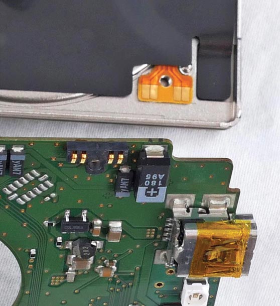
The connector to the spindle motor flex-cable is well-designed (Fig. 7). A screw goes right in the middle of the connector to ensure pressure is maintained on the contacts. All of the contacts look to be gold-plated. The black insulating separator is in its design position in this shot. It may also serve as sound damping. In addition, it may be conductive enough to provide shielding for the spindle motor, which radiates EMI as it runs.
 |
||
| Figure 7. | The four-pin connector for the spindle motor is a sophisticated design that connects to a flex circuit mounted in the case. |
|
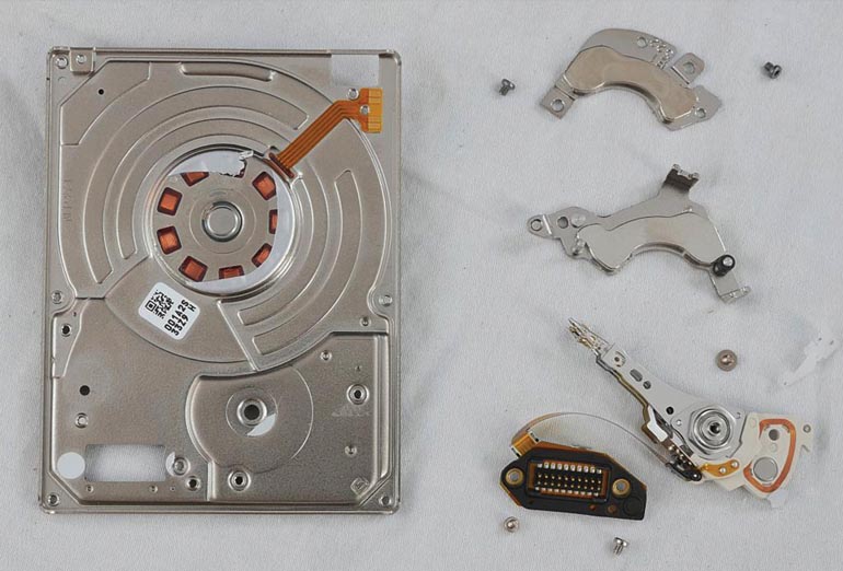
The spindle motor is epoxied in place to the sheet-metal case (Fig. 8). The read head flying arm and connector are made as a sub-assembly. This allows testing before final assembly. You can see the loop of wire that’s positioned between the magnets to make the head flying arm move. The magnets are rare-earth composition and very powerful. The flying arm was mounted to the case with a 3-pointed screw. My iFixIt precision screwdriver set had one of these bits, as well as minuscule Torx-head bits used elsewhere in the drive. The newer 64-bit kit looks even more capable.
 |
||
| Figure 8. | The case mounts the spindle motor and the flying head and magnet assembly, as well as the connector for the head motor and signal lines. |
|
 |
||
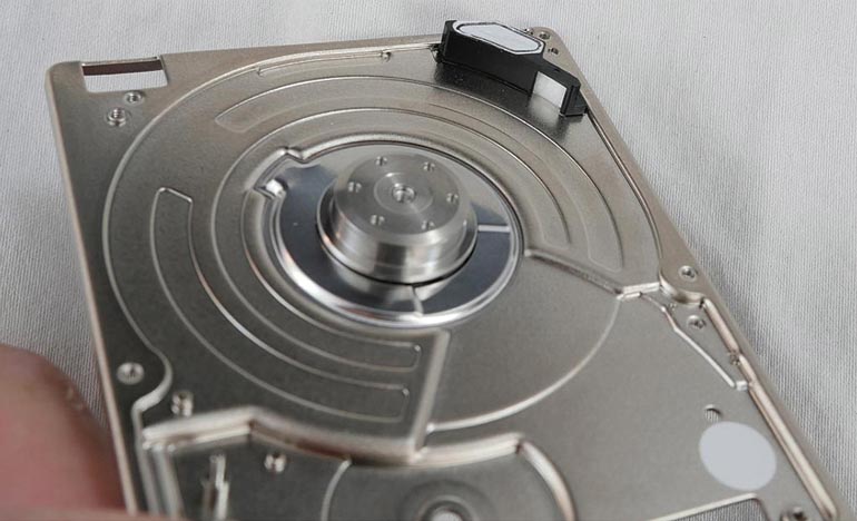
| Figure 9. | The function of the black plastic piece on the upper right of the case half is a mystery. | |
There was a mysterious black plastic piece inside the drive (Fig. 9). The underside was vented to the atmosphere. But the internal cavity so vented seems to be sealed from the inside of the disk. It may be the white film on top is a permeable membrane that allows the air pressure inside the drive to equalize to ambient. The small white pad is also a mystery. Its captivated by the black plastic piece, but I could not understand what it would be used for.
