A lot of the analog-circuit conversation these days is centered on low-power and thus low-voltage considerations. That makes sense for operational amplifiers (op amps), of course, since these basic analog building blocks often serve as a buffer or amplifier for low-level sensor signals that are often in the 1 V range.
Still, there’s a large slice of analog power-related circuitry devoted to control of higher voltages. In some cases, it’s a matter of supporting efficient power transfers, since higher voltages require less current for a given power level, and thus incur less IR voltage drop and I2R power loss. However, for many of these higher-voltage applications it is not an issue of the power itself; instead, it is just that due to the laws of physics, higher voltage is required even if the current is low or modest. Among the applications are the widely used piezoelectric transducers used for ultrasound systems, piezo-based precision nanometer-range positioners, avalanche photodiodes (APDs) in LIDAR systems, biasing of single photon avalanche diodes (SPAD), and semiconductor automatic test equipment (ATE).
 |
||
| Figure 1. | This basic circuit uses a pair of complementary discrete transistors to boost the output swing of a lower-voltage op amp. |
|
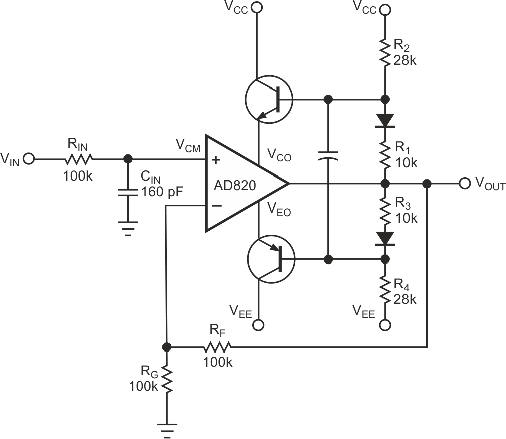
It wasn’t very long ago that adapting an op amp to deliver voltages at about 50 V or higher was a challenge. It was usually accomplished by starting with a standard op amp in the 15-to-24-V range, then boosting its output with discrete transistors. This could look simple in principle with complementary PNP and NPN devices (Figure 1). However, achieving symmetrical performance was difficult and the better circuit required more passive components (Figure 2).
 |
||
| Figure 2. | An improved voltage-boosting circuit requires significantly more components to ensure symmetrical and linear performance across the output’s swing range. |
|
Fully characterizing the performance across all load and other conditions was time consuming and needed analysis based on the unavoidable tolerances of these added components. There were also pre-packaged hybrid devices that were effective for the higher voltages; these used an op amp packaged with the requisite associated components all in a small package, which looked electrically like an op amp, but with higher-voltage capability, and overload and thermal protection as well.
Fortunately, in the last few years, IC vendors have worked to overcome the process limitations that restricted analog components to those lower voltages. For example, the Texas Instruments OPA462 high-voltage (180 V), high-current (30 mA typical, 45 mA maximum) op amp operates from a ±6 V (12 V) to ±90 V (180 V) bipolar supply and has a 6.5 MHz gain-bandwidth product and slew rate of 32 V/μs (Figure 3). The package’s diminutive size is quite impressive, with a body size of about 5×4 mm (plus external leads).
 |
||
| Figure 3. | The Texas Instruments OPA462 op amp can provide ±90 V outputs while delivering to 30 mA typical. | |
TI is not the only recent entry into the area of these higher-voltage op amps. Analog Devices has the ADHV4702-1, a 24 V-to-220 V precision op amp that can use symmetrical or non-symmetrical supplies (Figure 4). This op amp has a typical slew rate of up to 74 V/μs and 10-MHz small signal bandwidth. The 12-lead device measures just 7×7 mm and is compliant with the spacing called out by IEC 61010-1, ”Safety requirements for electrical equipment for measurement, control, and laboratory use – Part 1: General requirements” (references 2 and 3).
 |
||
| Figure 4. | The ADHV4702-1 from Analog Devices is a 220-V device that can use symmetrical or asymmetrical bipolar supplies. | |
Unfortunately, there isn’t much discussion or hands-on study of these higher-voltage op amps or design situations even in power-related EE programs. I know there is a lot of material to cover, and it’s easy to sit here at a keyboard and proclaim that such-and-such should be added to the curriculum when there are only 24 hours in the day and many demands on students’ and teachers’ time. Still, they have subtleties such as the need for a guard ring around the non-inverting input and to be driven to a potential which tracks the input to minimize leakage from nearby pins.
So, I wonder why there is this lack of attention. Is it because higher-voltage analog is viewed as a niche within a niche, and it’s more important for students to focus on the basics of op amps? Or is it that running a lab with higher voltages is a genuine risk, even if student labs do not have to adhere to the creepage and clearance mandates that apply to products offered for commercial sale (References 4 and 5)?
References
- Jim Williams, “Power Gain Stages for Monolithic Amplifiers,” AN-18, Analog Devices/Linear Technology Corp.
- “IEC 61010-1: IEC System of Conformity Assessment Schemes for Electrotechnical Equipment and Components (IECEE),” IEC 61010-1:2010.
- “IEC 61010-1, Edition 3,” Analog Devices.
- “Understanding PCB Creepage and Clearance Standards,” Tempo Automation.
- “Clearance and Creepage Rules for PCB Assembly,” Optimum Design Associates.
