It was a no brainer – at first. Circa 1985 equipment still in use by telcos, the DUT was a remote-operated twisted-pair telephone cable analyzer. We had extensively reverse-engineered and repaired several of these a couple years ago, the OEM was defunct. The customer was so happy with our previous work that another one of these antiques recently came in for repair.
As the SME (subject matter expert) who did the initial reverse engineering I was handed the project. Pulled out my notes and tried to refresh my memory with what I had studied 2 years ago. Easy fix – power supply problem. This was a simple DC-DC converter with no regulation feedback: –48 volts in to a push-pull center-tapped step down transformer, linearly regulated ±15 Vdc and +5 Vdc out (Figure 1). Several resistors were burned to a crisp, a collector-to-emitter clamp diode was shorted, the 7815 and 7915 linear voltage regulators had failed leaky to ground (fortunate since this hopefully spared the load circuits from damage), five electrolytic capacitors were dried out and measured open on the scope. Non-electrolytic capacitors all tested good. As a precaution, I replaced all power supply silicon, even those that still tested good since they had likely been stressed and were now prone to imminent failure.
 |
|
| Figure 1. | The circuit is deceptively simple. What could go wrong with this? |
The obsolete TIP51 NPN BJT push-pull driver transistors were a bit difficult to find replacements for, but finally found the NTE394 which looked electrically suitable. It was a larger TO-249 package instead of the original TO-218, but it was the same bolt-to-a-heatsink style and all mechanical dimensions looked workable. In this case the metal chassis enclosure itself was used as the heatsink.
The original TIP51 transistors used rubbery conforming thermal insulators and plastic shoulder washers to isolate their collector flanges electrically from the chassis, but these insulators were too small to be re-used with the new transistors. Each NTE394 came with a large mica insulator, requiring a thin layer of thermal compound to be spread on both sides of the insulator for adequate heat conduction. A certain type of thermal grease – Arctic Silver 5 – was stocked in our parts inventory, so I used it. At first I was bit concerned since this grease consisted of microscopic silver particles suspended in an “advanced polysynthetic oil”, but its data sheet stated it was not electrically conductive. The mica insulators supplied with the new NTE394s looked a bit beat-up, creased where they had been bent in shipping, but still in one piece so I used them.
Out of caution I did the first test-fire at 20 volts instead of the normal 48 volts – the smoke test is only successful if the DUT does not smoke. (Maybe it should be called an anti-smoke test). The scope on the collector of one of the switching transistors showed an oscillation for a few seconds (yeehaw!), then suddenly the oscillation stopped. Subsequent power-ups at higher voltages would result in ’squegging' – a short burst of a few cycles of oscillation as shown in Figure 2, then a pause for several milliseconds before repeating.
 |
|
| Figure 2. | The squegging repeated every few milliseconds. VIN is –48 V. Blue is Q1 base; red is Q1 collector; ground is Q1 emitter. |
That power supply led me on a wild ghost chase. To continue testing at the reduced 20 volts I temporarily reduced the 46K4 base bias resistor to enable the squegging again, hopefully without blowing anything up. Then followed the most frustrating, head-scratching, excruciatingly painful troubleshooting experience I've ever encountered.
The squegging was not consistent with supply voltage, even with the base bias resistor reduced. Sometimes it would start squegging at 18 volts, sometimes not until 30 volts. When not squegging it would draw only about 10 mA, both push-pull transistors biased barely into conduction, so obviously no shorted components.
To eliminate the possibility of excessive loading I removed the bridge rectifiers. The circuit still squegged.
With all defective components already replaced, could the problem be in the magnetics? No spare for the main transformer T1 (potted in a metal case, custom made and now obsolete), but T2 was several turns of magnet wire on a toroid core. Was there a shorted turn? Was the core somehow magnetized and saturating from the previous faults? Took it off the PCB and measured the inductance with the circuit of Figure 3.
 |
|
| Figure 3. | Measuring transformer inductance with a scope and square wave function generator. |
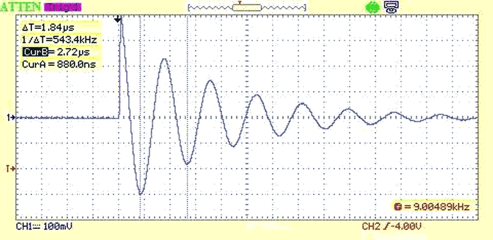
Figure 4 looks not too bad but is quite damped even with all windings unloaded. Shorting the other half of the primary winding caused the inductance to decrease drastically, proving that there were no shorted turns.
![Отклик трансформатора, индуктивность которого, рассчитанная по формуле L = 1/[(2πf)2C] при емкости C = 1 нФ, составляет 21.3 мкГ.](https://www.rlocman.ru/i/Image/2023/12/20/Fig_4.gif) |
|
| Figure 4. | The response of the DUT transformer with C = 1 nF the inductance calculates to 21.3 µH using the formula L = 1/[(2πf)2 C]. |
Because of the low voltage involved it was unlikely that the transformer was breaking down under actual operating conditions, and the toroid core was not electrically conductive so had not been zapped by a high voltage (lightening strike) surge. But there was still the question of possible core magnetization or an invisible crack, and since I had a few toroid cores of about the same size in the junk box I wound a few with the same turns count. The original core material type was unknown, but one of my jerry-rigged attempts came close, see Figure 5.
 |
|
| Figure 5. | Still 1 µs/div, the Amidon FT-50A-77 toroid material has higher inductance (85.9 µH) but is otherwise suitable. |
Unfortunately, the squegging continued, so I put the original T2 back onto the PCB and threw the others back into the junk box for future use.
Pulled the main transformer T1 off the PCB and did similar tests. Again shorting another winding caused the inductance to decrease drastically, proving that there were no shorted turns inside the transformer. But what was it doing under the higher voltage of normal operation?
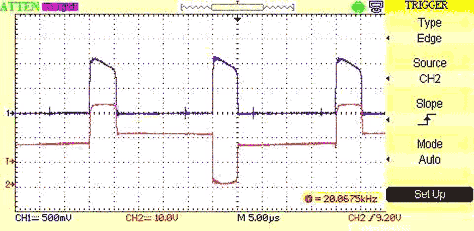
Note (in Figure 1) the T1 winding in series with the 82R5 resistor and 0.1 µF capacitor. I opened this branch up and wedged in (series) a small transformer (Midcom 50398, another junk box artifact) and drove it with a square wave from a function generator. This forced the circuit into continuous operation to get a better look at what was happening to the squelching of the squegging. The series 0.1 µF capacitor differentiated the square wave to limit the duty cycle of the transistors' on time, hopefully to a safe value that would not blow up the transistors with the continuous operation.
I reconnected T1 back into the circuit with some alligator clip wires. To measure transistor and transformer current I inserted a 1 ohm resistor into the emitter branch of the circuit and shorted the second 129 µH choke (the one in parallel with the diode and 27 ohm resistor) to remove its effects from the measurement. Current could then be read on the scope as the voltage dropped across the 1 ohm resistor. I should have seen a rising edge on each current pulse due to the unloaded transformer inductance. Instead, I saw what you see in Figure 6.
With no way to obtain another T1 of the same type, I pulled a common mode choke off a junk boxed scrapped PCB with about the same inductance rating for a temporary test. A common mode choke has two identical windings and would make a good test substitute for the DUT T1 center-tapped unloaded primary to verify my test setup. I removed the original T1 from the circuit and jerry-rigged this choke to the DUT using the same alligator clip wires.
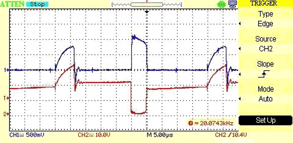
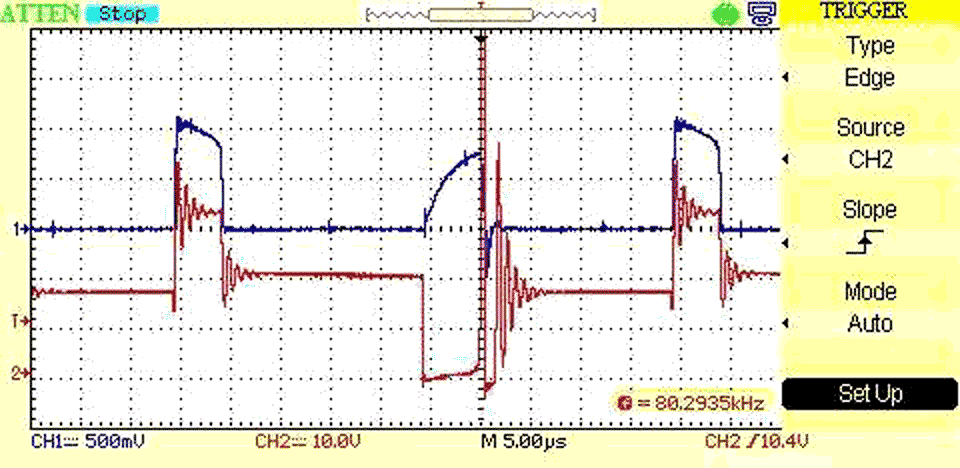
The results were an eye-opener. See Figures 7 and 8.
The common mode choke load showed very different switching characteristics between the two push-pull drive transistors, unlike the original transformer. Swapping the choke windings made no difference, the problem stayed with Q2. Very obviously something was wrong with the Q2 portion of the circuit.
Finally with a solid clue to work with, I poked around again with an ohmeter. Both Q1 and Q2 collectors measured 21.5 ohms to the chassis. I now had the culprit – must be that 1 µF capacitor between T1 center tap and chassis that had previously checked good.
But nope – pulling that cap off the pcb made no difference. And there was no other connection to the chassis in that circuit, in spite of what the ohmeter was telling me.
Then a nasty suspicion hit, and with the ohmeter still connected I backed off the mounting screw of Q2 about a quarter turn. The meter jumped to about 8K ohms.
I backed off the mounting screw of Q1 – the meter jumped to infinity – open circuit.
Somehow the collector mounting flanges of the transistors were leaking through the mica insulators to the chassis. I had known there was a small crease where the insulators had been bent, but that should not have caused any problem even if the cracks did penetrate completely through the insulators because the thermal grease is non-conductive – the data sheets aid so.
Took another look at the data sheet. The thermal grease is non-conductive if smeared on a pcb. It is intended for heatsinks attached to CPUs; our staff uses this grease when mounting heatsinks onto BGAs. In this use, even if it was conductive it would not matter.
But the data sheet says nothing about what happens when the grease is compressed under the much higher pressure of a screw holding a transistor flange to a heatsink. Remember the grease contains microscopic silver particles immersed in an oil base – were these silver particles coming in contact with each other when squeezed tightly? And if so, when squeezed into a crack that fully penetrates a mica insulator this grease could cause exactly the problem I was seeing.
I emailed the Arctic Silver company and received a phone call a couple hours later. Yes, they confirmed that their product would become electrically conductive when under pressure.
I then obtained two more intact mica insulators and some real thermal grease that did not contain silver particles – you know, that white stuff everyone refers to as bird-poop. No more problems after that.


