The principle behind testing the impulse response of circuits is simple: hit them with a sharp pulse and see what happens. As usual, Wikipedia has an article detailing the process (Ref. 1). This notes that the ideal pulse – a unit impulse, or Dirac delta (Ref. 2) – is infinitely high and infinitely narrow with an area beneath it of unity, so it’s infinitely tricky to generate, which is just as well, considering the effects one would have on everything from protection diodes to slew rates. Fortunately, it’s just an extreme case of the normal or Gaussian distribution, or bell curve, which is a tad easier to generate or at least emulate and, which this DI shows how to do.
In the real world, the best testing impulses come from arbitrary waveform generators. An older technique is to filter narrow rectangular pulses, but if you change the pulse width, the filter’s characteristics also need to be varied to maintain the pulse shape. The approach detailed in here avoids that problem by generating raised cosine pulses (not to be confused with raised-cosine filters) which are close enough to the ideal to be interesting. But let’s be honest: simple rectangles, slightly slugged to avoid those slew-rate problems, are normally quite adequate.
Producing our pulses
We make our pulses by taking the core of a squashed-triangle sine-wave oscillator (Ref. 3) and adding some logic and gating so that when triggered, it produces single cycles which rise from a baseline to their peak and then fall back again, following a cosine curve. The schematic in Figure 1 shows the essentials.
 |
|
| Figure 1. | A simple oscillator with some added logic generates single pulses when triggered. |
How the oscillator works
The oscillator’s core is almost identical to the original, though it looks different having been redrawn. Its basic form is that of an integrator-with-Schmitt, where C1 is charged up through resistors R2 and R3 until its voltage reaches a positive threshold defined by D3, which flips A1b’s polarity, so that C1 starts to discharge towards D4’s negative threshold. D1/D2 provide bootstrapping to give linear charge/discharge ramps while compensating for variations in D3/D4’s forward voltages with temperature (and supply voltage, though that should not worry us here). The resulting triangle wave on A2’s output is fed through R7 into D5/D6 which squash it into a reasonable (co)sine wave (<0.5% THD). The diode pairs’ forward voltages need to be matched to maintain symmetry and so minimize even-harmonic distortion. A4 amplifies the signal across D5/6 so that the pulse just spans the supply rails, thermistor Th1 giving adequate compensation for temperature changes.
If A2’s output were connected directly to R1’s input, the circuit would oscillate freely – and we’ll allow it to later on – but for now we need it to start at its lowest point, make one full cycle, and then stop.
In the resting condition, U2a is clear and A1b’s output is high, producing a positive reference voltage across D3. (That’s positive with respect to the common, half-supply internal rail.) That voltage is inverted by A2a and applied through U1a to R1, so that there is negative feedback round the circuit, which stabilizes at the negative reference. (Using a ‘4053 for U1 may seem wasteful, but the other sections of it will come in handy in Part 2.)
When U2a’s D input sees a (positive-going) trigger, its outputs change state. This way, U1a connects R1 to A1b’s (still high) output, starting the cycle; the feedback is now positive. After a full cycle, A1b’s output goes high again, triggering U2b and resetting U2a, thus stopping the cycle and restoring the circuit to its resting state. The relevant waveforms are shown in Figure 2.
 |
|
| Figure 2. | Some waveforms from the circuit in Figure 1. |
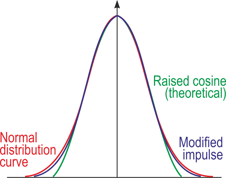
Comparing raised cosines with ideal normal-distribution pulses is instructive, and Figure 3 shows both. While most of the curves match reasonably, the bottom third or so is somewhat wanting, though it can be improved on with some extra complexity – but that’s for later.
 |
|
| Figure 3. | A comparison between an ideal normal-distribution curve and a raised cosine, including the output from Figure 1. |
As previously mentioned, and apparent from the schematic, the circuit works as a simple oscillator if U2a’s operation is disabled by inhibiting its trigger input and jamming its preset input low to force its Q high. U1a now connects A1b’s output to R1, and the circuit runs freely. Apart from being useful as a feature, this helps us to set it up.
Trimming the oscillator
A few trims, in the oscillator mode, are needed to get the best results.
- R3 must be set to give equal tri-wave amplitudes at the maximum and minimum settings of R2, or distortion will vary with frequency (or pulse width). Set R2 to max (lowest frequency) and R3 to min (towards the right on the schematic), then measure the amplitude at A1’s output. Now set R2 to min and adjust R3 to give the same amplitude as before. (Thanks to Steve Woodward for the idea behind this.)
- R7 defines the drive to the squashing diodes D5/6 and thus the distortion. Using a ‘scope’s FFT is preferable: adjust R7 to minimize the third and fifth harmonics. (The seventh remains fairly constant.) Failing that, set R7 so that the voltage across the diodes is precisely 2/3 of the tri-wave’s value. As a last resort, a 30k fixed resistor may be close enough, as it was in my build.
- Set the output level using R9. The waveform should run from rail to rail, just shaving the tips of the residual pips (which are mainly responsible for those seventh harmonics) from the peaks. Don’t overdo it, or the third and fifth harmonics will start to increase. This depends on using RRO op-amps for at least A1b and A2b and carefully-split rails for symmetry.
Once trimmed as an oscillator, it’s good to go as a pulse generator, which relies on exactly the same settings, so that each pulse will be a single cycle of a cosine wave, offset by half its amplitude.
The schematic in Figure 1 gives the bare bones of the circuit, which will be fleshed out in Part 2. The op-amps used are Microchip MCP6022s, which are dual, 5-V, 10-MHz CMOS RRIO devices with <500 µV input offsets. Power is at 5 V, with the central “common” rail derived from another op-amp used as a rail-splitter: shown in Figure 4 together with a suitable output buffer.
 |
|
| Figure 4. | A simple rail-splitter to derive the 2.5-V “common” rail, and an output level control and buffer with both AC- and DC-coupled outputs. |
C1 can be switched to give several ranges, allowing use from way over 20 kHz (for 25 µs pulses, measured at half their height) down to as low as you like. R3 then also needs to be switched; see Figure 5 for a three-range version. (The lowest range probably won’t need an HF trim.) While the tri-wave performance is good to around 1 MHz, the squashing diodes’ capacitance starts to introduce waveform distortion well before that, at least for the 1N4148 or the like.
 |
|
| Figure 5. | For multi-range use, timing capacitor C1 is switched. To trim the HF response for each range, R3 must also vary. |
Improving the pulse shape
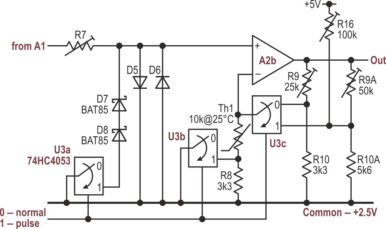
Now for that extra complexity to improve the pulse shape. In very crude terms, the top half of the desired pulse looks (co)sinusoidal but the bottom more exponential, and that part must be squashed even further if we want a better fit. We can do that by bridging D6 with a series pair of Schottky diodes, D7 and D8. The waveform’s resulting asymmetry needs offsetting, necessitating a slightly higher gain and different temperature compensation in the buffer stage A2b. These mods are shown in Figure 6.
 |
|
| Figure 6. | Bridging D6 with a pair of Schottky diodes gives a better fit to the desired curve, though the gain and offset need adjusting. |
In this mode, R16 sets the offset and R9A the gain. The three sections of U3 will:
- Switch Schottkys D7/8 into circuit
- Select the gain- and offset-determining components according to the mode
- Short out R8 to place the thermistor directly across R12 and optimize the temperature compensation of the pulse’s lower half
Figure 7 shows the modified pulse shape. Different diodes or combinations thereof could well improve the fit, but this seems close enough.
 |
|
| Figure 7. | The improved pulse shape resulting from Figure 6. |
To set this up, adjust R16 and R9A (which interact; sorry about that) so that the bottom of the waveform is at 0 V while the peaks are at a little less than 5 V. Because the top and bottom halves of each pulse rely on different diodes, their tempcos will be slightly different. The 0-V baseline is now stable, but the peak height will increase slightly with temperature.
To be continued…
By now, we’ve probably passed the point at which it’s simpler, cheaper, and more accurate to reach for a microcontroller (Arduino? RPi?) and add a DAC – or just use a PWM output, at these low frequencies – equip it with look-up tables (probably calculated and formatted using Python, rather like the reference curves in these Figures) and then worry about how to get continuous control of the repetition rate and pulse width. Or even just buy a cheap AWG, which is cheating, though practical.
But all that is a different kind of fun, and we have not yet finished with this approach. Part 2 will show how to add more tweaks so that we can also generate well-behaved step-functions.