You’ve got an apparently simple design requirement on your latest AC-line powered project: provide a distinctly illuminated indicator to show that the unit is plugged into the line and that power is “on,” meaning that the line is good, and the unit is switched on. That’s needed as both a user convenience and a quick troubleshooting clue if the unit appears “dead” when presumably switched on.
One obvious approach is to keep it simple and just draw a little power from any available DC rail in the product to provide around 20 mA to drive a red LED. If a suitable rail isn’t available, you could add a small circuit to drive that LED (Figure 1).
 |
|
| Figure 1. | It’s not hard to drive an LED indicator from the AC line, but it requires many active and passive components. |
However, there’s a problem with either of these solutions. First, there’s the issue of credibility and confidence regarding safety implications. If for any reason the circuit driving that DC rail has a fault and the LED doesn’t illuminate, you could have a safety scenario where the user thinks the AC line is cut off and the circuit is not live; but it actually is.
Even if that’s not a concern, the separate indicator circuit is relatively costly and complicated for what it does, even if the bill of materials (BOM) is small. If there isn’t a DC rail that you can tap and you do need a step-down transformer, or you need that transformer for regulatory-safety isolation, things are no longer simple and cheap.
So, you figure there must be a lower-cost, all-passive way to directly connect an LED to the AC line – and there are several. One “cheat” is to use a voltage-dropping resistor to limit the voltage and AC-line current to the LED requirements (around 20 mA). But this offers inconsistent performance, has technical risks like high resistor-power dissipation, and yields an LED flickering at 50/60 Hz.
Another possibility is the “capacitor-dropper” (cap-drop) supply which is used in some commercial designs when a low-current DC rail is needed from an AC source (Figure 2).
 |
|
| Figure 2. | A “capacitor-dropper” circuit can also be used to drive an LED directly from the AC line; despite its apparent simplicity, it’s actually a circuit with subtleties and also has some regulatory/safety issues (upper: 230 VAC and lower: 110 VAC). |
Again, these circuits bring regulatory and safety concerns and issues and would have to be physically separated from other parts of the design. To meet safety codes such as those from UL, the entire circuit and its tiny circuit board (if any) must be arranged physically, so the user is protected if there is a fault to the chassis. Furthermore, this approach requires larger, more-costly, higher-voltage passive components, especially the capacitors, which must provide a safety margin of about twice the line-voltage peak.
The reality is that adding an “AC live” subcircuit using LEDs is not as easy in practice as it may appear in theory. You have the needed raw power but transforming it into what you need is more difficult both technically and from a regulatory standpoint.
Go back to the future with neon lamps
Fortunately, there is a time-tested and highly reliable solution: use a small neon bulb and current-limiting resistor, which can be connected directly to the AC line (115 or 230 VAC), as shown in Figure 3. While this circuit must also be properly insulated, it’s so simple and small that it can be covered in a single piece of heat-shrink tubing or a similarly insulated setup.
 |
|
| Figure 3. | All it takes to use a neon lamp with an AC line as its power source is a current-limiting series resistor, as shown in the schematic (left); the physical implementation of the schematic diagram is also a simple interconnect (right). |
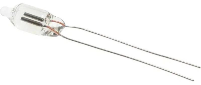
Neon bulbs – more properly called lamps, since that’s their function – have been around since the early 1900s and they come in a variety of sizes and styles. The most common size in general use for indicators by far is NE-2 lamp with a 12-mm length and 5-mm diameter (Figure 4).
 |
|
| Figure 4. | The widely used NE-2 neon lamp measures about 12 mm in length and 5 mm in diameter. |
The value of the current-limiting resistor depends on the neon lamp size, desired brightness, and its minimum/maximum current ratings. This value is typically 50-to-220 kΩ for 120 VAC mains and twice that value for 220 VAC with an NE-2 neon lamp. The power rating for the resistor is also low, on the order of ¼ watt or less. It doesn’t get simpler than that – or more reliable.
The neon bulb has a typical life between 20,000 and 50,000 hours, comparable to an LED. Neon lamps are also very rugged and are not affected by vibration, mechanical shock, or frequent on/off operation. They generally operate over a wide temperature range from –40 °C to +150 °C and are not susceptible to damage from voltage transients, which are due to high-voltage static discharges or line transients. In some ways, neon lamps are similar to miniature gas-discharge tubes (GDTs) used for circuit protection.
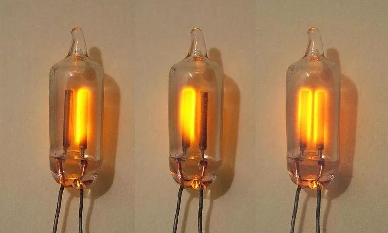
Note that neon lamps are non-polarized DC devices with two symmetrical electrodes. When DC is applied, one electrode glows; if the DC is reversed, the other electrode glows (Figure 5). When connected to an AC source, the electrodes alternate glowing; the eye integrates this and does not see the flicker.
 |
|
| Figure 5. | The neon lamp is a polarity-agnostic DC-driven discharge device with a cathode that glows, as can be seen from this “triple” image (left to right) of a positive polarity on the left wire (cathode on right), on the right wire (cathode on left), and driven by an AC waveform (cathode alternating). |
The inherent compatibility with DC sources makes the neon indicator a viable choice for higher-voltage DC rail designs, which are increasingly being used with solar panels, battery energy storage systems (BESS), and DC distribution.
Physics is complex, use is trivial
The voltages and currents needed to initiate the discharge and subsequent glow depend on various factors such as ambient temperature, specific gas mix, and even ambient lighting. When a starting voltage (“initiation” or “striking”) is applied, typically 55-110 volts AC or 90-140 volts DC, the gas ionizes and starts to glow, thus permitting a very small current to travel from one electrode to the other.
Once the bulb initiates the discharge as the gas ionizes, the maintaining (sustaining) operating voltage will drop to about 10 to 20 volts below the initial striking voltage. It’s called a “negative resistance” characteristic and leads to some interesting non-indicator applications.
The lamp will stay on until the voltage drops to below 50 V. The leakage current through a small neon lamp, when off, is very low, on the order of a few hundred microamps. The operating current after the lamp initiates the glow is also low for a small size bulb, on the order of several milliamps.
Physicists have studied the neon-discharge action in detail for over one-hundred years and have identified each of the phase transitions and associated reason for it (Figure 6).
The striking voltage is affected by the specific gas mixture and pressure in the lamp. Usually, the gas is a Penning mixture (named after Frans Michel Penning), which is 99% to 99.5% neon and 0.5% to 1.0% argon at a pressure of 1–20 torrs (0.13–2.67 kPa); this mixture has lower striking voltage than pure neon.
 |
|
| Figure 6. | This detailed view of the three discharge zones shows some subtle effects and transition points. |
No need to even DIY
There’s an easier way to design-in a neon lamp as an AC power-on indicator rather than wiring up the lamp and resistor and then insulating the assembly. You can get the lamp and resistor as a panel indicator in a ready-to-use sealed panel-mount housing with choice of wire leads, solder terminal, or slip-on quick-connect terminations.
Taking convenience and simplifying physical arrangement even further, many rocker switches are offered with integral neon indicators. This combination of rocker switch with internal lamp also brings an intuitive “human interface” aspect to design and its operation, since the switch’s action and the associated illumination are visually and physically linked.
There are many cases where an old technology can still be legitimate or even best solution to address modern design challenges. While LED-based indicators have largely obsoleted neon ones for low-voltage solutions, neon is still a very viable option for AC-line indications.
Neon-based lamps are available in multiple package options, including bare bulb, panel-mount, and rocker switch, further enhancing their utility and versatility for many design situations.