Derek MacLachlan, Keithley Instruments
Test & Measurement World
Step 3
This step addresses building the test system and verifying its performance, including a number of techniques that can be used to improve measurement quality.
Once a system builder has picked appropriate equipment, cables, and fixtures, and established that the equipment’s specifications can meet the requirements, it’s time to assemble it and verify its performance once step at a time. It is essential to check that each piece of test equipment has been calibrated within its specified calibration period, which is usually one year. If the instrument will be used for making voltage measurements, placing a short across the inputs of the meter will provide an indication of any offset errors. This can be directly compared to the specifications from the data sheet. If the instrument will be used for current measurements, then checking to see the current level with the ammeter open circuit will give an indication of offset current. Again, this can be directly compared to the specifications from the data sheet. Next, include the system cabling and repeat the tests, followed by the test fixture, then the device under test (DUT), repeating the tests after each addition. If the performance of the system does not meet the application’s requirements, this «one step at a time» approach should help identify what is causing the problems.
Then, check the system timing to ensure there are sufficient delays to allow for settling time, and reassess it to make sure it satisfies the application’s speed goals. Insufficient delay times between measurements can often create accuracy and repeatability problems. In fact, this is among the most common sources of error in test systems, and it’s especially evident when running the test at speed produces a different result than when performing the test step by step or manually.
Although inductance can affect settling times, capacitance in the system is a more common problem. In a manual system, a delay of 0.25 to 0.5 seconds will seem to be instantaneous. But in an automated test system, steps are typically executed in a millisecond or less, and even the simplest systems may require delays of five to ten milliseconds after a change in stimulus to get accurate results.
Large systems with lots of cabling (and therefore, lots of cable capacitance, and/or those that measure high impedances ( = RC) may require even longer delays or special techniques like guarding. Coaxial cable typically has capacitance in the range of 30 pF per foot.
The common solution is to provide sufficient delays in the measurement process to allow for settling. Delays of several milliseconds are commonly needed, but some applications may require even longer delays. To address this need, most Keithley instruments include a programmable trigger delay.
Guarding is one technique for dealing with capacitance issues, reducing leakage errors and decreasing response time. Guarding consists of a conductor driven by a low impedance source surrounding the lead of a high impedance signal. The guard voltage is kept at or near the potential of the signal voltage.
Leading Sources of Measurement Error
Although all systems are unique, the following sources of error are among the most common:
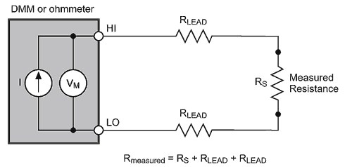 |
| Figure 3a. |
- Lead resistance. For resistance measurements, especially at lower resistances, it is important to take into account the resistance of the test leads. In the example shown in Figure 3a, the two-wire ohms method is being used to determine the resistance. A current source in the meter outputs a known and stable current, and the voltage drop is measured within the meter. This method works well if the resistance to be measured is very much greater than the lead resistance. However, what if the resistance to be measured is much closer to the lead resistance or even less? Using four-wire measurements (Figure 3b) will eliminate this problem. The voltage drop is now measured across the resistor, instead of across the resistor and leads. The input resistance of the voltmeter tends to be very high in comparison to the resistance to be measured; therefore, the lead resistances on the voltmeter path can be ignored. If, however, the resistance to be measured is very high, and approaching the resistance of the voltmeter, then an electrometer or specialized meter with extremely high input resistance may be required.
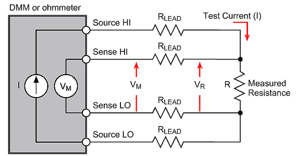 |
| Figure 3b. |
- Thermoelectric EMFs in connections. In any measurement system, any connections made that are of dissimilar metals will produce a thermocouple. A thermocouple is essentially a device of two dissimilar metals that generates a voltage that varies with temperature. These qualities can be put to good use when using thermocouples to monitor temperature, but in standard test system, they result in the introduction of unwanted voltages. As temperatures vary, so does the magnitude of the unwanted voltages. Table 1 lists some examples of the types of voltages that can be generated. Even when connecting copper to copper, there are typically enough differences in the composition of the two pieces of metal that voltages will be generated. If the magnitude of these errors is significant in comparison to the value to be measured, the offset-compensated ohms technique can help eliminate the effect.
Table 1. Thermoelectric Potentials
|
Materials
|
Potential
|
|
Cu – Cu
|
≤0.2 µV/°C
|
|
Cu – Ag
|
0.3 µV/°C
|
|
Cu – Au
|
0.3 µV/°C
|
|
Cu – Cd/Sn
|
0.3 µV/°C
|
|
Cu – Pb/Sn
|
1-3 µV/°C
|
|
Cu – Si
|
400 µV/°C
|
|
Cu – Kovar
|
40 µV/°C
|
|
Cu – CuO
|
1000 µV/°C
|
This offset-compensated ohms technique is built into many Keithley instruments. When this feature is enabled, the measurement cycle now consists of two parts (Figure 4): the first part is measuring the voltage with stimulus current switched on, the second part is to measure it with the stimulus current switched off. Subtracting the latter from the former will subtract out the errors due to thermoelectric EMFs. Therefore, this technique will effectively eliminate accuracy issues due to temperature drift.
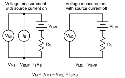 |
| Figure 4. |
- External interference. External interference introduces both AC and DC errors into signal measurements. The most common form of external noise «pick-up» is 50 Hz or 60 Hz line pick-up, depending on where in the world the measurements are being made. Picking up millivolts of noise is not uncommon, especially when measurements are made near fluorescent lights. The signal components of noise superimposed on a DC signal being measured may result in highly inaccurate and fluctuating measurements. As shown in Figure 5, the measured value will very much depend on where the measurement is carried out in relation to the sine wave. Many modern instruments allow users to set the integration period in relation to the number of power line cycles. In other words, a setting of 1 NPLC will result in the measurement being integrated for 20 milliseconds (if 50 Hz) and 16.67milliseconds (if 60 Hz), which will eliminate any mains generated noise. The performance improvements this feature make possible are often dramatic.
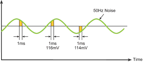 |
| Figure 5. |
- Theoretical measurement limits. The laws of physics provide a fundamental limit of how low a signal can be resolved because every system will generate some level of voltage and current noise. Figure 6 identifies the levels of voltage that are impossible to measure, as well as the levels approaching the theoretical limits of voltage measurement.
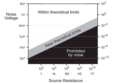 |
| Figure 6. |
Step 4
Once the test system has been built and verified, it’s ready to begin making measurements in which users can have confidence. However, it’s important to recheck the performance of any test setup on a regular basis. Because of component drift, the accuracy of an instrument will vary over time, so ensure that the instrumentation is calibrated regularly.
