Editor’s note:
Jim McLucas, author of the Design Idea Circuit measures capacitance or inductance wanted to respond to some discussion about using this Design Idea. Please see the following that may help.
This is an analysis of the effect of parasitic capacitance (e.g. probe cap.) on the measurement of inductance. The effect can cause a large error if the measurement frequency is approaching the resonant frequency of LX||CP.
 |
||
| Figure 1. | Test setup to measure inductance, with unknown inductance, LX, and probe capacitance, CP. | |
When measuring an inductance with the setup shown in Figure 1, the probe capacitance will decrease the accuracy of the measurement. The unavoidable probe capacitance in parallel with the unknown inductance will modify the inductive reactance to produce an apparent inductance.
The reactance, XL, of the apparent inductance, L, when a probe capacitance, CP, is in parallel with the unknown inductance, LX, is (neglecting losses in LX and CP):
 |
(1) |
when f < f0. (f0 is the resonant frequency of LX||CP.)
Therefore, the ratio VIN/VOUT will be modified as shown in equation 2.
 |
(2) |
The accuracy of the measurement can be improved by making the reactance of CP much greater than that of the reactance of LX. Chose a frequency, f, which makes this true. Assume a value for LX and then select a value for m in equation 3. Then compute the maximum useable frequency for that value of m. Frequencies lower than the calculated value will reduce the measurement error; higher frequencies will increase the error.
For XCp = mXLx
 |
(3) |
Now calculate a value for R:
 |
(4) |
Adjust the frequency of the signal generator to make VIN/VOUT equal to 2.
Then compute the value of L:
 |
(5) |
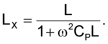
The corrected value of LX can be calculated from:
 |
(6) |
When m ≥ 20 the measurement error will be < 5%. It may take a couple of iterations to optimize the measurement, if high accuracy is desired.
